
Lane recognition system and method using defog sensor

Active Publication Date: 2015-06-25
HL KLEMOVE CORP
View PDF3 Cites 2 Cited by
  • Summary
  • Abstract
  • Description
  • Claims
  • Application Information

AI Technical Summary

Benefits of technology

This invention provides a system and method for recognizing lanes in a special environment where frost or demister is formed on a windshield using a defog sensor. The system analyzes the sensor signal and identifies final lane information through image processing. This helps to accurately recognize lanes and reduces the risk of accidents. The system also removes unnecessary edge groups to acquire the lane information.

Problems solved by technology

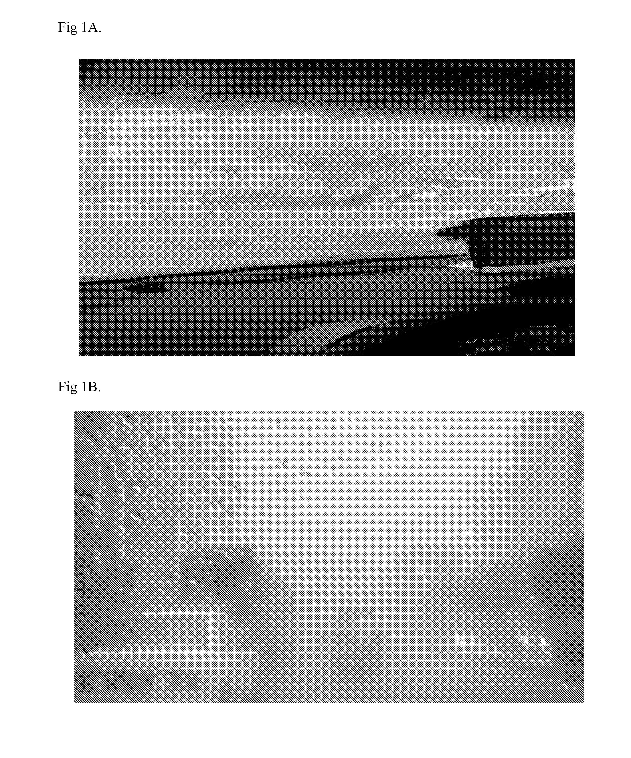
However, although various related techniques have been developed, the lane recognition precision of the lane departure warning system and method may be significantly degraded in a special environment in which frost or demister is formed on the windshield of a vehicle as illustrated in FIG. 1A or 1B.
Furthermore, when a lane is misrecognized due to the frost or demister, the lane departure warning system based on the misrecognized lane may malfunction to increase the risk of an accident during operation.
However, since the air-conditioning system is implemented separately from the operation of the lane recognition system, the defogging system does not contribute to the improvement of lane recognition precision.

Method used


Image

  • Lane recognition system and method using defog sensor
  • Lane recognition system and method using defog sensor
  • Lane recognition system and method using defog sensor

Examples


Embodiment Construction

[0040]In the accompanying drawings, illustration of each component may be exaggerated for convenience in description and clarity. Furthermore, the terms as used herein are defined by taking functions of the invention into account and can be changed according to the custom or intention of users or operators. Therefore, definition of the terms should be made according to the overall disclosures set forth herein. Furthermore, embodiments of the present invention are only examples of components described in claims, and do not limit the scope of the present invention, and claims must be analyzed on the basis of the technical idea throughout the present specification.

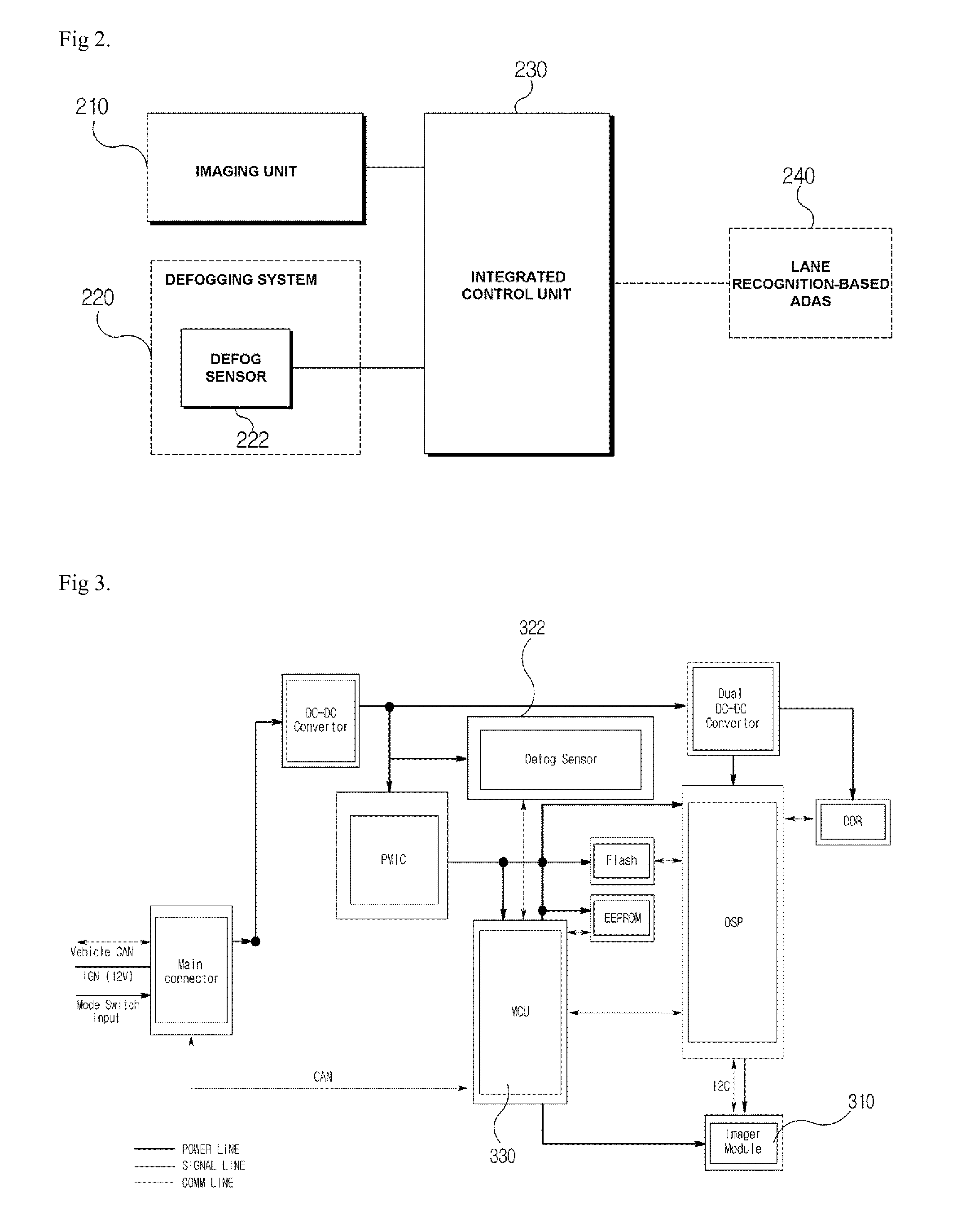
[0041]FIG. 2 is a schematic configuration diagram of a lane recognition system using a defog sensor according to an embodiment of the present invention.

[0042]Referring to FIG. 2, the lane recognition system using a defog sensor according to the embodiment of the present invention includes a defog sensor 222, an imaging unit 2...


PUM


Abstract

Disclosed herein is a lane recognition system using a defog sensor, including: a defog sensor mounted in a defogging system of a vehicle; an imaging unit mounted on a windshield of the vehicle so as to image the front of the vehicle; and an integrated control unit configured to analyze a defog sensor signal received from the defog sensor, process an image signal received from the imaging unit based on the analyzed defog sensor signal, and acquire lane information.

Description

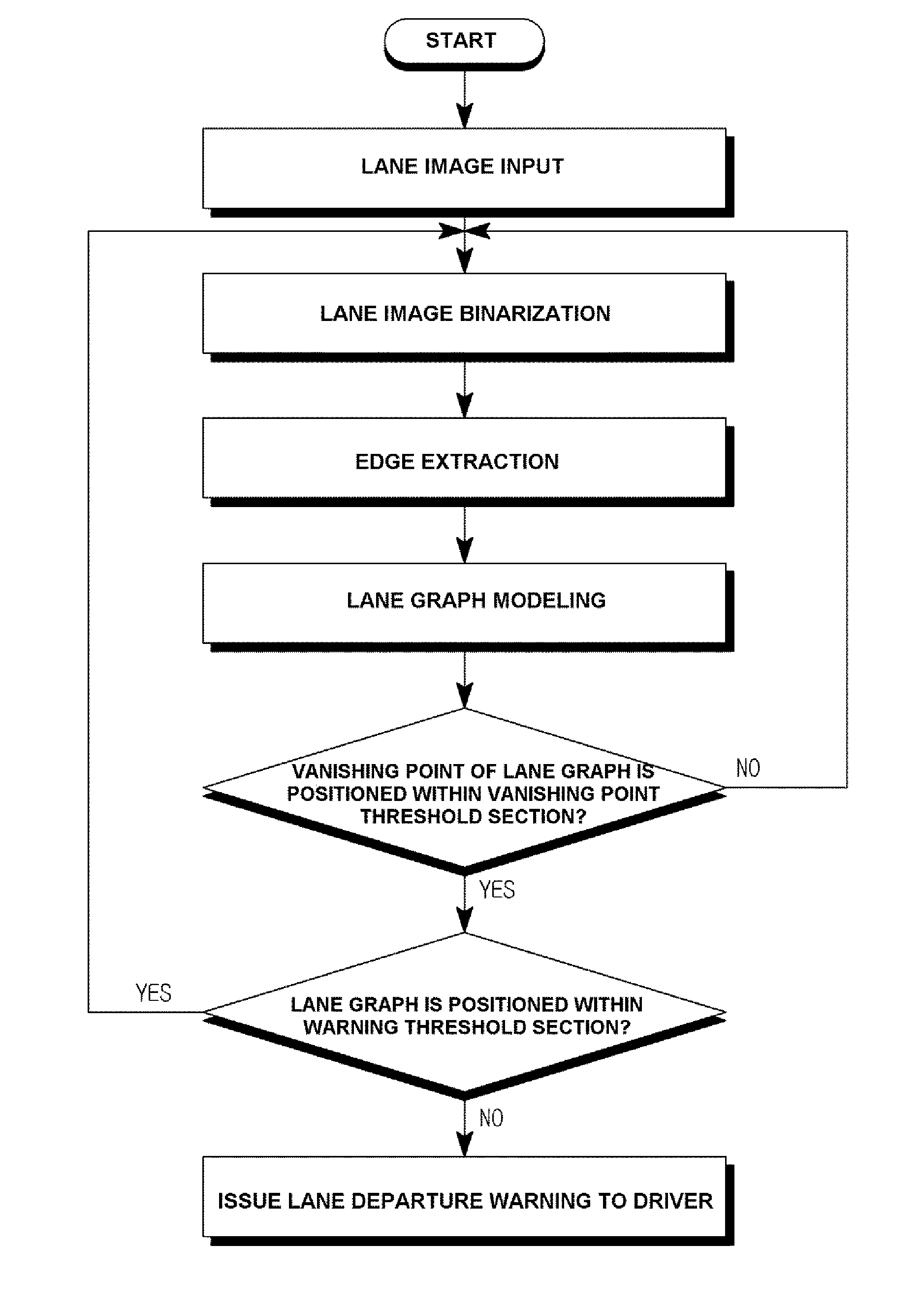
CROSS-REFERENCE(S) TO RELATED APPLICATIONS[0001]This application claims priority to Korean Patent Application No(s). 10-2013-0162367, filed on Dec. 24, 2013, the disclosure(s) of which is(are) incorporated herein by reference in its(their) entirety.BACKGROUND OF THE INVENTION[0002]1. Field of the Invention[0003]Exemplary embodiments of the present invention relate to a lane recognition system and method using a defog sensor, and more particularly, to a lane recognition system and method using a defog sensor, which analyzes a signal of the defog sensor and acquires final lane information through image processing based on the analyzed signal.[0004]2. Description of the Related Art[0005]Recently, in the automobile industry, research has been actively conducted on the development of technology related to an advanced driver assistance system (ADAS) for supporting a driver's driving ability.[0006]In particular, many ADASs based on lane recognition technology have emerged. Representative e...

Claims


Application Information

Patent Timeline
IPC IPC(8): H04N7/18B60K35/00
CPCB60K35/00B60K2350/2013B60K2350/962B60K2350/1076G06T7/0042G06K9/00798B60W10/30G06T7/0081G06K9/00791B60H1/00785G06V20/588G06V20/56B60W30/12G06T7/13G06T7/536G06T2207/30256G06T5/70B60K35/29B60K2360/21B60K2360/1868
Inventor PAEK, SEUNG BUM
Owner HL KLEMOVE CORP
Learn More