Modular speaker component

Active Publication Date: 2015-06-25
TGI TECH
View PDF6 Cites 7 Cited by
  • Summary
  • Abstract
  • Description
  • Claims
  • Application Information

AI Technical Summary

Benefits of technology

[0023]6. The vibration directions of all the passive diaphragm units intersect the central axis of the fixed part. Further, the sum of all the passive diaphragm components perpendicular to the central axis of the fixed part is zero; this setup causes the tangential vibration for the entire speaker in the horizontal direction to achieve balance during operation. This greatly weakens the horizontal shifting of the speaker body during large movements. It makes the speake

Problems solved by technology

Particularly for some special venues, the speaker cannot be made too big after taking into consideration factors such as structure and appearance.
Further, due to constraints, it cannot simply be placed in the environment to stick out all alone.
A very large proportion of speakers have custom structures so uniformity is hard.
It is difficult to satis

Method used


Image

  • Modular speaker component
  • Modular speaker component
  • Modular speaker component

Examples


embodiment 1

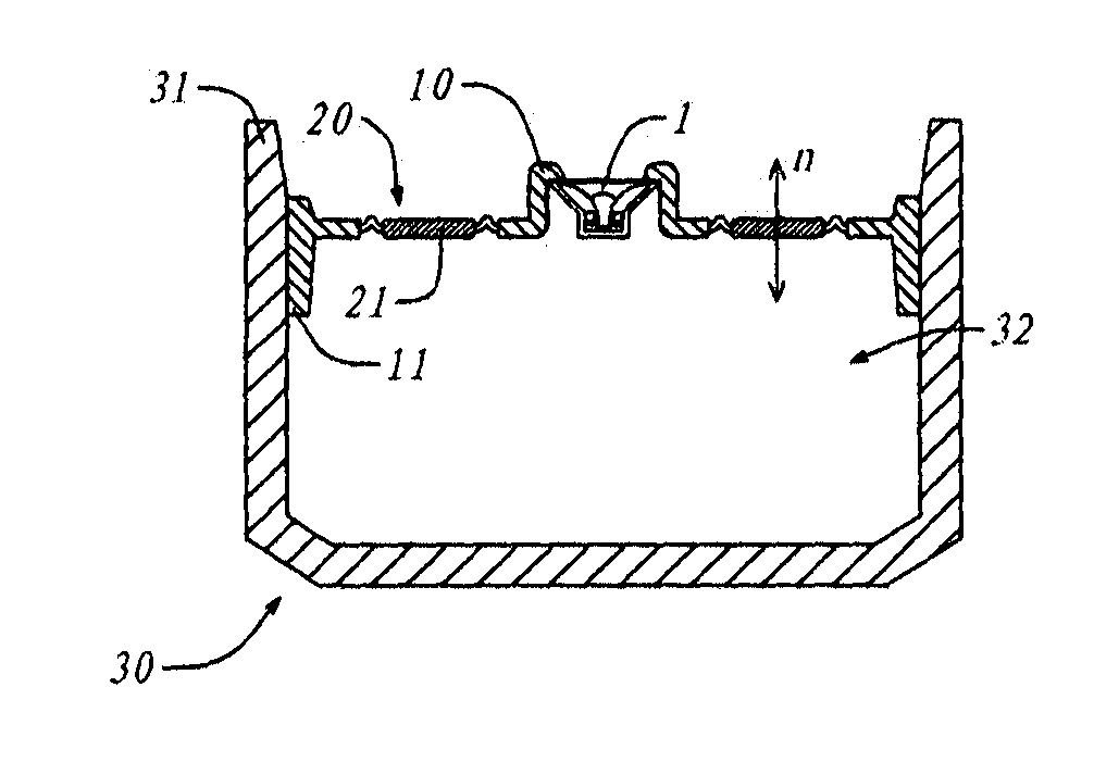
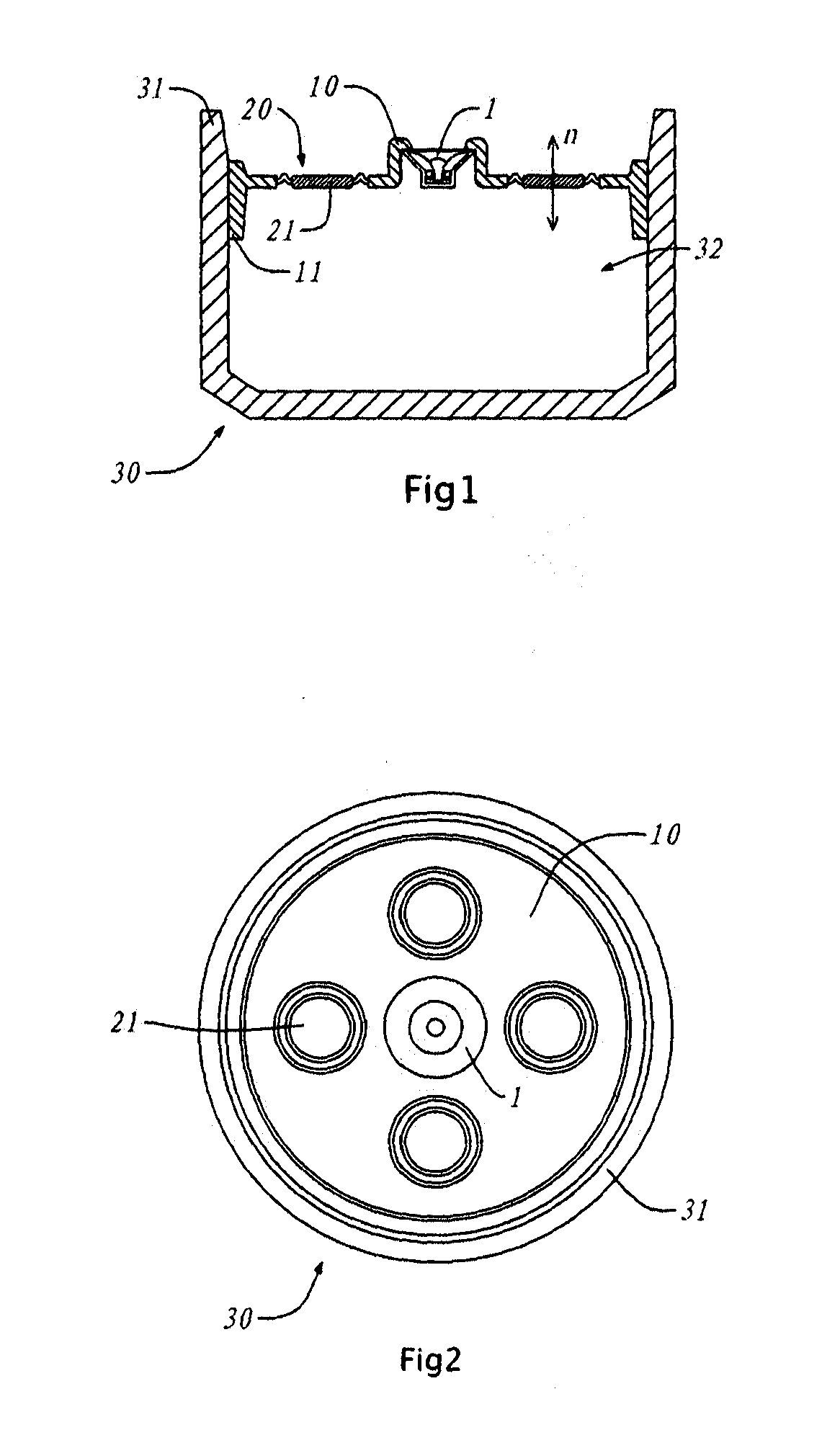
[0041]As per FIG. 1, the side cutaway view diagram for the use of embodiment 1 of this invention on a ceramic groove-shaped container; FIG. 2 is the schematic top view diagram for the embodiment shown in FIG. 1; the following explanation for embodiment 1 of this invention is with reference to these two diagrams.

[0042]Fixed part 10 has a disc-shaped thin-walled structure. A moving coil type active loudspeaker unit 1 is loaded at its center. Its cone hole faces upward; four passive diaphragm units 20 are distributed at the periphery of active loudspeaker unit 1 which is on top of fixed part 10. Fixed part 10 forms a circle together with sealed connection part 11 at its periphery. Using the plugging method, it is secured within opening 31 of rigid container 30. Further, the central axis of fixed part 10 and the central axis of active loudspeaker unit 1 are the same; also, the four passive diaphragm units 20 are rotationally symmetric around the aforementioned central axis. In particula...

embodiment 2

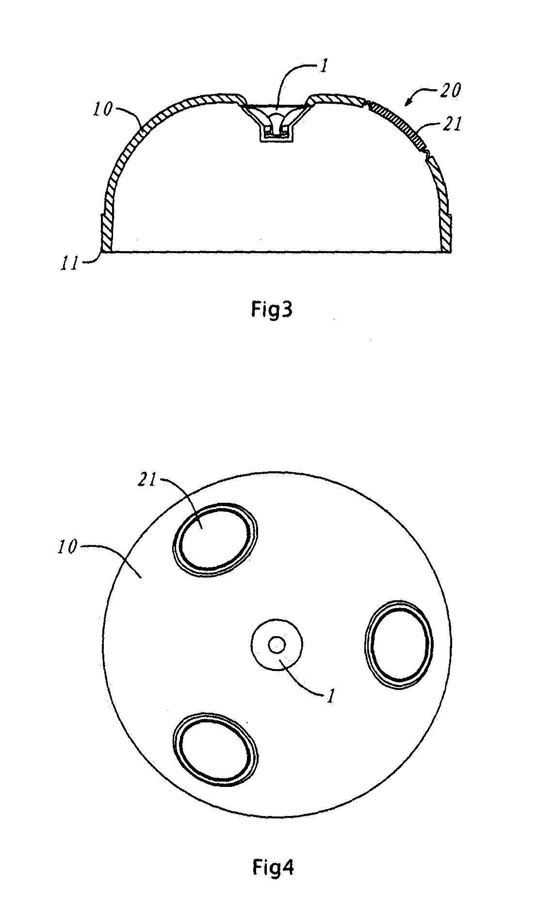
[0047]As per FIG. 3, the side cutaway view diagram for embodiment 2 of this invention; FIG. 4 is the schematic top view diagram for the embodiment shown in FIG. 3; FIG. 5 is the schematic cutaway view diagram for the use of the embodiment shown in FIG. 3 on a standard glass jar; the following explanation for this embodiment 2 is with reference to these three diagrams.

[0048]In this embodiment 2, there are three passive diaphragm units 20. Like embodiment 1, they are rotationally symmetric relative to active loudspeaker unit 1 that has the same central axis as fixed part 10; the vibration directions of all the passive diaphragm units 20 intersect the central axis of fixed part 10; further, the sum of all the passive diaphragm 20 components perpendicular to the central axis of fixed part 10 is zero; this setup causes the tangential vibration for the entire speaker in the horizontal direction to achieve balance during operation. This greatly weakens the horizontal shifting of the speake...

embodiment 3

[0050]As per FIG. 6, the side cutaway view diagram for embodiment 3 of this invention; FIG. 7 is the top view diagram for the embodiment shown in FIG. 6; the following explanation for embodiment 3 is with reference to these two diagrams.

[0051]The form of fixed part 10 for this embodiment 3 is similar to that for embodiment 2. It is an upward protruding structure; active loudspeaker unit 1 is still located at the central axis of fixed part 10 and the back loading method is used. The difference is that the form of passive diaphragm units 20 is a ring-shaped structure. The part within the inner ring is filled by active loudspeaker unit 1; the outer ring reaches sealed connection part 11. Such a form allows the entire fixed part 10 to obtain maximum use, such that its effective vibration area is the largest. It has outstanding performance at low frequencies and the coloration is minimized at the same time too. In particular, a plan using such kind of ring-shaped passive diaphragm units ...


PUM


Abstract

This invention discloses a kind of modular speaker component. A characteristic is that it includes a fixed part. This fixed part has a thin-walled structure. An active loudspeaker unit and passive diaphragm units are installed on it. Another characteristic is that it includes a sealed connection part. This sealed connection part is fixed on the said fixed part and it has sealing material; the said sealed connection part aligns, connects and secures the said fixed part to the opening of a rigid container. This causes the said fixed part and the rigid container to jointly form an airtight resonant space. The fixed part integrates the active loudspeaker unit and passive diaphragm units on top and combines with the sealed connection part fixed on it to form overall a universal high sound quality module that is unaffected by the rigid container. In a plan based on a small volume, it can also exhibit outstanding performance at medium and low frequencies; it can very conveniently form a complete high performance speaker with the rigid container, and satisfy the shape constraint requirements for the speaker in various application environments with different styles.

Description

CROSS-REFERENCE TO RELATED APPLICATIONS[0001]This is a U.S. national stage application of the International Patent Application No. PCTSG2013000116, filed 22 Mar. 2013, which claims priority to Chinese Patent Application No. 201210131536.8, filed 28 Apr. 2012, both of which are incorporated herein by reference in their entirety.FIELD OF THE INVENTION[0002]This invention involves the modular component of a kind of modular speaker.BACKGROUND OF THE INVENTION[0003]As a piece of electric-acoustic conversion equipment, the speaker has a wide variety of forms. Particularly for some special venues, the speaker cannot be made too big after taking into consideration factors such as structure and appearance. Further, due to constraints, it cannot simply be placed in the environment to stick out all alone. And so, the form of the speaker body should be made such that it is similar to the environmental elements. Such special venues are very varied and they can range from e.g. museums to exhibiti...

Claims


Application Information

Patent Timeline
IPC IPC(8): H04R7/20
CPCH04R7/20H04R1/24H04R1/2834
Inventor LI, SHIHUANG
Owner TGI TECH
Why Eureka
Try Eureka