
Handover With Mobile Relays

a mobile relay and handover technology, applied in the field of handover methods, can solve the problems of relatively low speed of mobile relays, and achieve the effects of good neighbour cell signal quality, poor signal quality of link to the ue, and poor signal quality of neighbour cell (potential donor base station)

Inactive Publication Date: 2015-06-25
FUJITSU LTD
View PDF5 Cites 16 Cited by
  • Summary
  • Abstract
  • Description
  • Claims
  • Application Information

AI Technical Summary

Benefits of technology

The present invention provides a wireless communication method that allows mobile devices to switch between different base stations for better connectivity. This is done by exchanging information between the source and target base stations, or the donor base stations if applicable. The switch is triggered based on the signal quality of the neighboring cells or the potential donor base station. The technical effect of this invention is to improve the reliability and performance of wireless communication networks.

Problems solved by technology

However, such mobile relays move with relatively low speed, which also allows other users such as pedestrians (outside of the vehicles) with low speed to access these mobile relays.
The key issue in this scenario is how to support handovers of the UEs which are necessitated by the movement either of mobile relays or of UEs.

Method used


Image

  • Handover With Mobile Relays
  • Handover With Mobile Relays
  • Handover With Mobile Relays

Examples


case 1

)

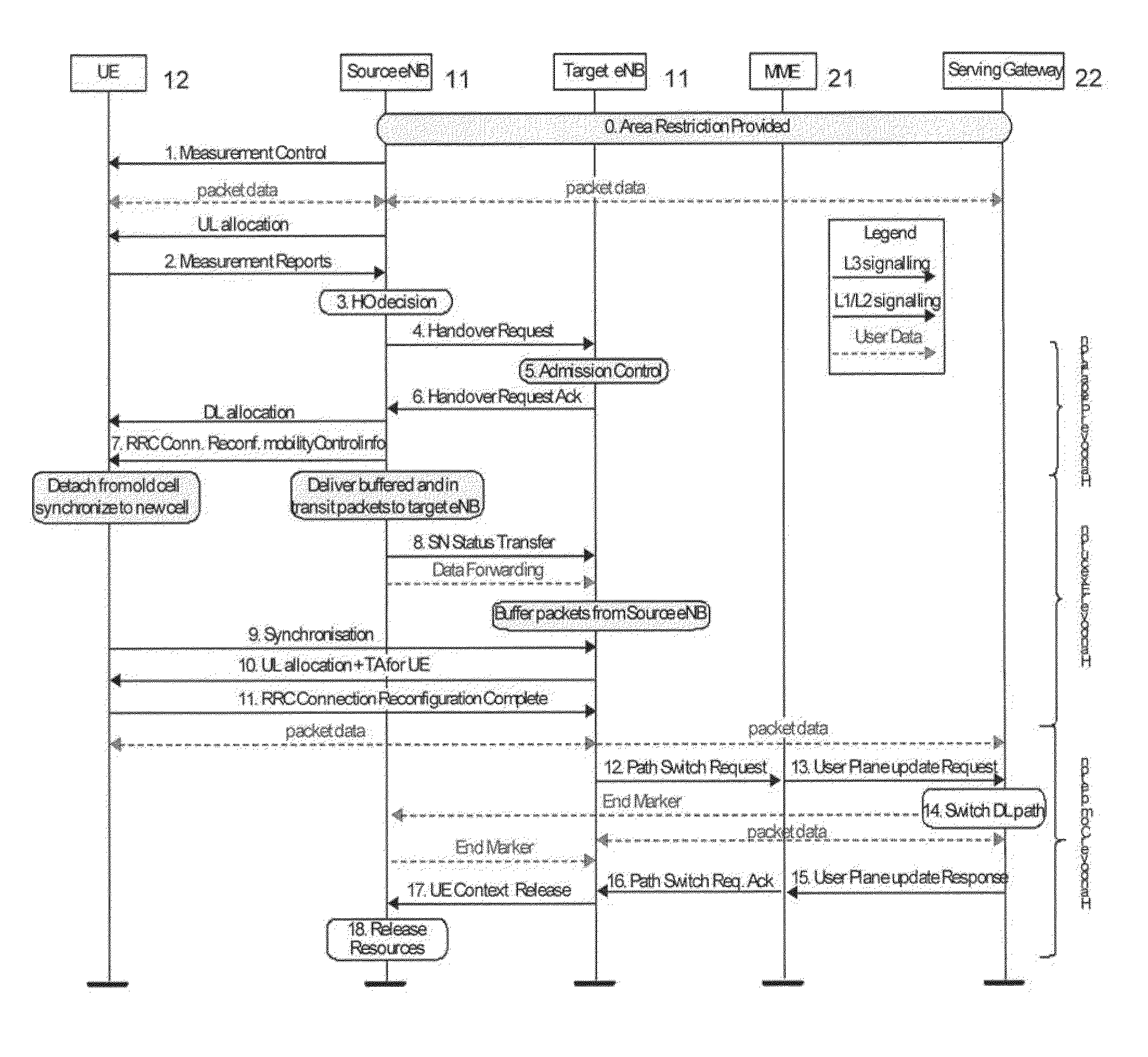
[0091]2.1. In case 1), the UE sends measurement reports to the serving eNB (e.g. Cell_A in FIG. 8) that handles control signalling.

[0092]3.1 Cell_A makes HO decision to initiate the handover procedure towards the most suitable neighbour cell MR_2. Because the Cell_A continues handling this UE's control signalling, only data traffic needs to be handed over to the target cell. For this purpose, Cell_A sends cell activation request to MR_2 (that is a mobile relay currently connected the Cell_A), in which the concerned UE's context is included as well as the current serving cell for data traffic MR_1′.

[0093]4.1 MR_2 performs admission control, and sends acknowledgement to confirm the handover.

[0094]5.1 Cell_A sends de-activation request to MR_1′ asking MR_1′ to handover the data traffic of the concerned UE to the target cell MR_2. MR_1′ acknowledges the request.

[0095]6.1 Cell_A sends data plane only handover command to the UE and asks the UE to connect to target cell MR_2 for data traf...

case 2

)

[0098]2.2. In case of 2), the MR_1′ sends measurement reports to the serving eNB (e.g. Cell_A in FIG. 9) that handles control signalling when the signal quality of the link to the UE is worse than a certain threshold.

[0099]3.2 Cell_A makes HO decision based on the measurement report for MR_1′ concerning the UE. Taking into account of the UE's report, Cell_A initiates the handover procedure towards the most suitable neighbour cell MR_2. Because the Cell_A continues handling this UE's control signalling, only data traffic needs to be handed over to the target cell. For this purpose, Cell_A sends cell activation request to MR_2 (that is a mobile relay currently connected the Cell_A), in which the concerned UE's context is included as well as the current serving cell for data traffic MR_1′.

[0100]4.2-8.2. These are the same as steps 4.1-8.1 mentioned above.

case 3

)

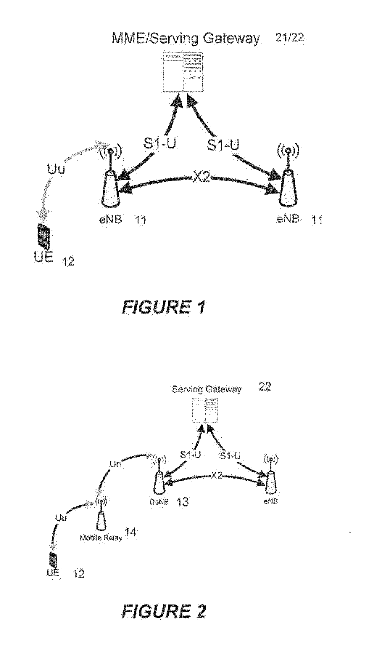
[0101]FIG. 10 shows the process of handover by Cell_A of UEs currently served both by itself (for control plane signalling) and by MR_1′ (for data traffic transmission). Such handovers need to take place before Cell_A hands over MR_1′ itself to Cell_B (not shown here).

[0102]2.3. In case of 3), the MR_1′ sends measurement reports to its donor base station when the signal quality of a neighbour cell (i.e. Cell_B in FIG. 10) is much better than the current donor base station (i.e. Cell_A).

[0103]3.3 Before Cell_A starts handover preparation for the MR_1′ towards Cell_B, it needs to handover to MR_2 the UEs currently served by both itself (for control plane signalling handling) and MR_1′ (for data traffic transmission). Cell_A makes HO decision for such UEs based on the measurement report from the UE and initiates the handover procedure towards the most suitable neighbour cell MR_2. Because the Cell_A continues handling this UE's control signalling, only data traffic needs to be handed ...


PUM


Abstract

A method to provide mobility support of UEs (12) that are served by mobile relay base stations (14), by providing handover of a UE (12) for data traffic only between two mobile relay base stations. This is achieved by information exchanging between the source and target mobile relay stations of the concerned UE in handover, and / or the corresponding donor base stations (13, 11) if applicable. The handover is triggered by any of the following: based on UE's measurement report, the signal quality of a neighbour cell is better than the current serving cell; based on the measurement of the serving mobile relay base station, the signal quality of the link to the UE is worse than a certain threshold; or based on the measurement of the serving mobile relay base station, the signal quality of a neighbour cell (potential donor base station) is much better than the current donor base station.

Description

CROSS-REFERENCE TO RELATED APPLICATIONS[0001]This application is a continuation of International Patent Application No. PCT / EP2013 / 066006, filed Jul. 30, 2013, now pending, and claims priority to European Patent Application No. 12183655.5, filed Sep. 10, 2012, the contents of each are herein wholly incorporated by reference.FIELD OF THE INVENTION[0002]This invention generally relates to wireless communication systems and in particular, to a handover method in such systems.BACKGROUND OF THE INVENTION[0003]Wireless communication systems are widely known in which subscriber stations communicate wirelessly in cells provided by base stations. Next generation wireless communications systems such as the Universal Mobile Telecommunications System (UMTS) and the UMTS Long Term Evolution (LTE) aim to offer improved services to the user compared to the existing systems. These systems are expected to offer high data rate services for the processing and transmission of a wide range of informatio...

Claims


Application Information

Patent Timeline
Patent Type & Authority Applications(United States)
IPC IPC(8): H04W36/30H04W36/00
CPCH04W36/30H04W36/0094H04W36/0055H04W36/08H04W84/047H04W36/0058H04W36/302H04W36/0061H04W36/22H04W36/0016
Inventor LI, ZHAOJUNVADGAMA, SUNIL KESHAVJI
Owner FUJITSU LTD
Learn More