
Apparatus and method for receiving transmit wave

a transmit wave and apparatus technology, applied in the direction of television system, transmission monitoring, receiver monitoring, etc., can solve the problems of unfavorable signal quality of transmit waves in all wave receiving systems, and achieve the effect of preventing effective degradation of receiving performance, deteriorating signal quality, and large signal level

Inactive Publication Date: 2006-07-11
PIONEER CORP
View PDF6 Cites 0 Cited by
  • Summary
  • Abstract
  • Description
  • Claims
  • Application Information

AI Technical Summary

Benefits of technology

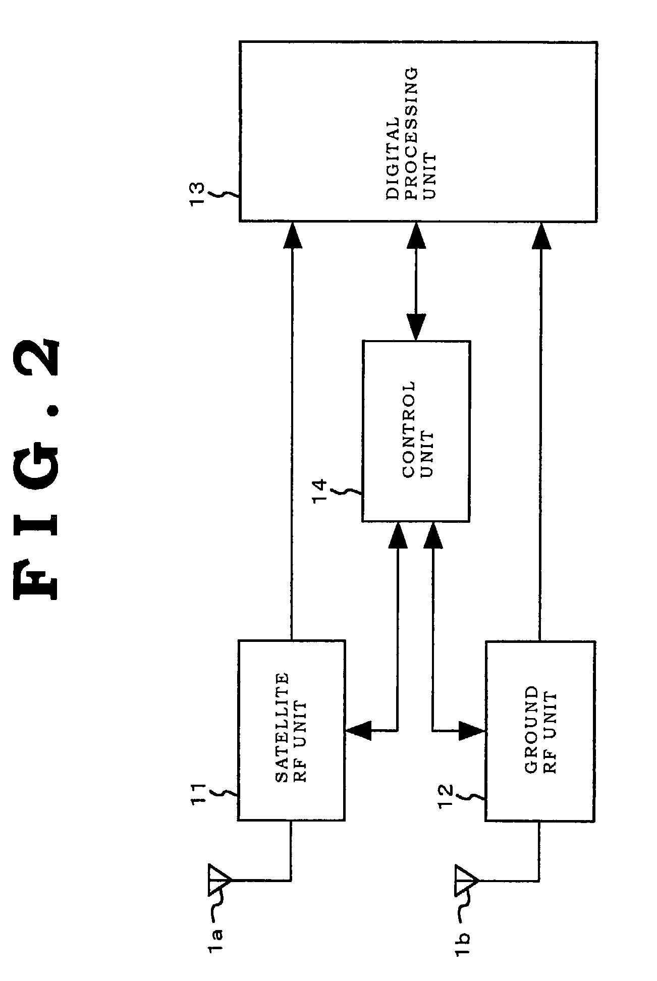
The present invention provides a transmit wave receiving apparatus that can prevent degraded receiving performance due to adverse influence from a certain radio station system. The apparatus monitors signal levels and signal qualities of transmit waves received from multiple wave transmitting systems and controls the wave receiving device accordingly. This prevents the adverse effect of a certain radio station system on other radio station systems. The apparatus can also monitor error rates and set a reference value for judgment, ensuring favorable signal quality. The apparatus can be used in a digital broadcast receiving system and can improve receiving performance under a condition where satellite and ground systems are mixed. The method includes receiving transmit waves, monitoring signal levels and signal qualities, and controlling the wave receiving operation accordingly. The technical effects of the invention include preventing degraded receiving performance and improving signal quality in a broadcast receiving system.

Problems solved by technology

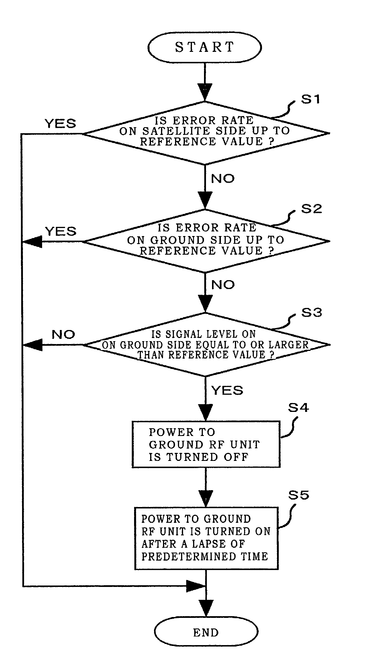
The control is made so as to halt a wave receiving operation for the transmit wave having a large signal level for a predetermined period of time, when it is judged from monitoring results by the signal monitoring device that the signal qualities of the transmit waves in all of the wave receiving systems are unfavorable.

Method used


Image

  • Apparatus and method for receiving transmit wave
  • Apparatus and method for receiving transmit wave
  • Apparatus and method for receiving transmit wave

Examples


Embodiment Construction

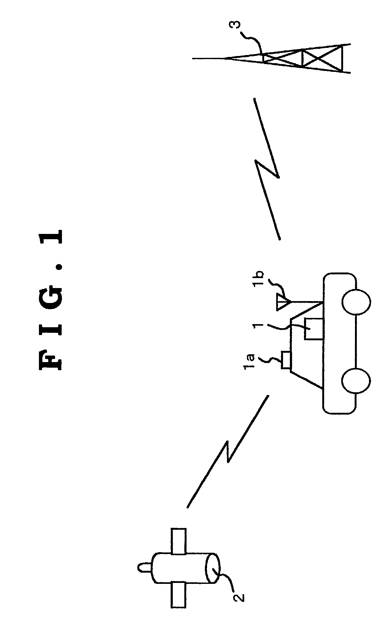
[0023]Now, embodiments of a transmit wave receiving apparatus of the present invention will be described in detail below with reference to the accompanying drawings. In the embodiment described below, the present invention is applied to a broadcast receiving system in which broadcast information is received through two systems, which are provided on a satellite and the ground.

[0024]FIG. 1 is a schematic descriptive view illustrating a structure of a broadcast receiving system of the embodiment of the present invention. The broadcast receiving system as shown in FIG. 1 includes a broadcast receiving apparatus 1 utilized in a movable body such as a vehicle, a satellite 2 provided with broadcast transmitting equipment serving as the first wave transmitting system and a ground station 3 provided as the second wave transmitting system to transmit broadcast information. The waves transmitted from the satellite 2 and the ground station 3 are allocated to different frequency bands from each...


PUM


Abstract

A transmit wave receiving apparatus comprises a wave receiving device, a signal monitoring device and a wave receiving control device. The wave receiving device receives transmit waves, which are transmitted from wave transmitting systems. The signal monitoring device monitors signal levels and signal qualities of the transmit waves, which are received by the wave receiving device. The wave receiving control device controls the wave receiving device so as to halt a wave receiving operation for the transmit wave having a large signal level, when it is judged from monitoring results by the signal monitoring device that the signal qualities of the transmit waves in all of the wave receiving systems are unfavorable.

Description

BACKGROUND OF THE INVENTIONField of the Invention[0001]The present invention relates to an apparatus and method for receiving transmit waves, which are utilized in a wave receiving system, which permits receiving of transmit waves through a plurality of systems.[0002]A broadcast receiving apparatus, which is mounted on a movable body such as a vehicle for purposes of receiving broadcast information is recently becoming pervasive. With respect to a device for transmit waves on the air to such a broadcast receiving apparatus, a satellite provided with wave transmitting equipment can be utilized, in addition to ground stations established on the ground. Movement of the broadcast receiving apparatus, which is receiving the broadcast information, varies radio environment, leading to a possibility of degradation of receiving performance. It is therefore effective to constitute a broadcast receiving system, which permits the broadcast receiving apparatus to receive the same broadcast infor...

Claims


Application Information

Patent Timeline
Patent Type & Authority Patents(United States)
IPC IPC(8): H04H1/00H03D7/16H04B1/16H04B7/02H04L69/40H04N5/44H04N5/46
CPCH03D7/161H04B17/309H04B17/21
Inventor OHSAWA, SUSUMU
Owner PIONEER CORP
Learn More