Liquid ejecting apparatus

Active Publication Date: 2015-07-02
SEIKO EPSON CORP
View PDF6 Cites 1 Cited by
  • Summary
  • Abstract
  • Description
  • Claims
  • Application Information

AI Technical Summary

Benefits of technology

The patent is about a device that efficiently heats a liquid on a medium (such as paper) with minimal energy while reducing damage to the medium. This is achieved by using a medium support unit with low thermal conductivity, which prevents thermal energy from leaking into the support unit and allows for efficient heating of the liquid. Additionally, a blower unit with high air velocity helps to dry the liquid while preventing bending of the liquid droplets. These technical effects enable the device to heat the medium with high energy efficiency and reduced damage.

Problems solved by technology

Since the medium is heated when being pushed to the suction hole, the medium is drawn into the suction hole according to a degree of thermal energy at the time of the heating, and there is a concern of being damaged.

Method used


Image

  • Liquid ejecting apparatus
  • Liquid ejecting apparatus
  • Liquid ejecting apparatus

Examples


embodiment (refer to figs.1 to 6)

Embodiment (Refer to FIGS. 1 to 6)

[0049]Hereinafter, a liquid ejecting apparatus according to an embodiment of the invention will be described in detail with reference to accompanying drawings.

[0050]First, (1) a schematic configuration of the liquid ejecting apparatus according to the embodiment will be described, and (2) a configuration and an operation form of a medium support unit which is a main part of the invention will be described in detail.[0051](1) Schematic Configuration of Liquid Ejecting Apparatus (Refer to FIGS. 1 and 2)

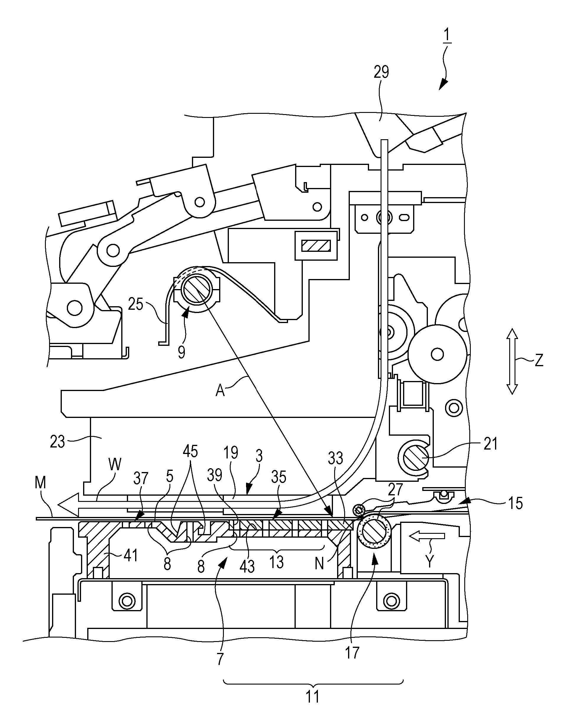
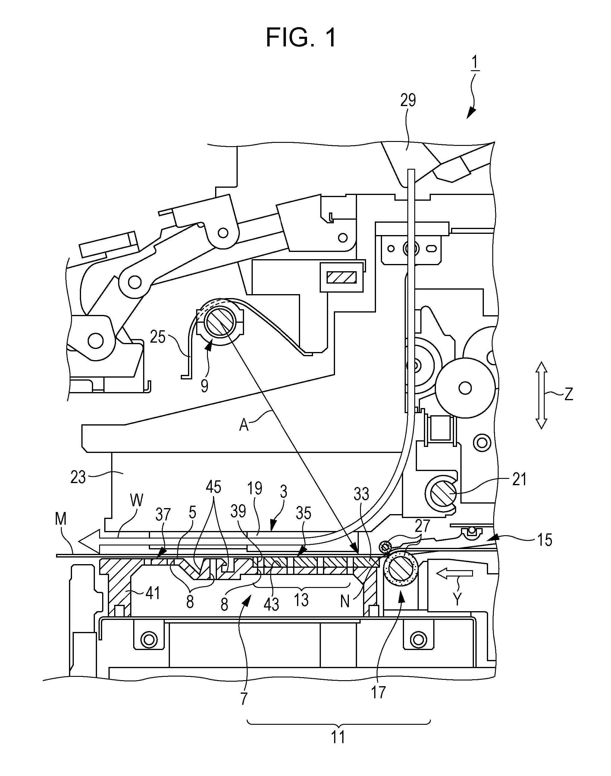
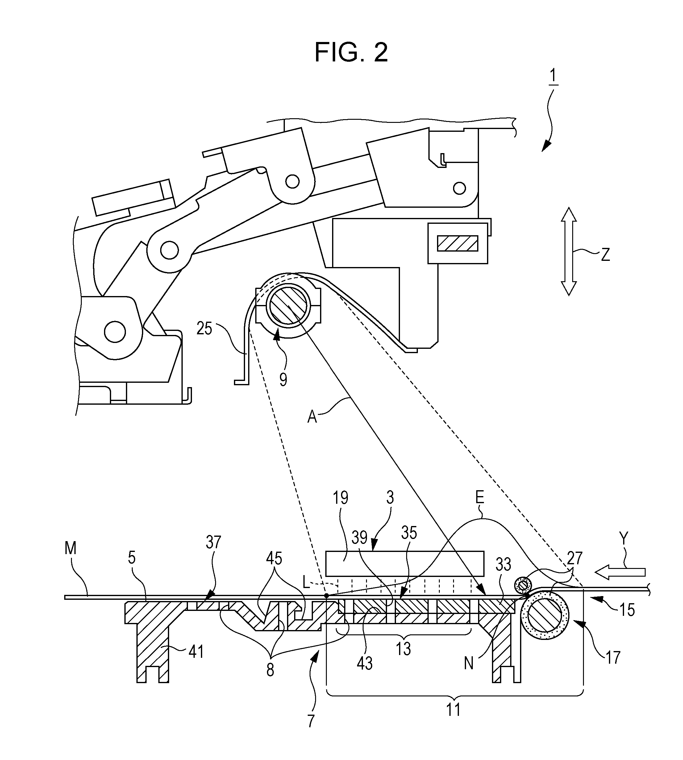
[0052]A liquid ejecting apparatus 1 according to one embodiment of the invention is basically configured by a medium support unit 7 including a supporting face 5 which supports a medium M onto which liquid L is ejected, and a heating unit 9 which can heat the liquid L from the side opposite to the supporting face 5 of the medium M which is in a state of being supported by the supporting face 5. In other words, the liquid ejecting apparatus 1 includes th...


PUM


Abstract

A liquid ejecting apparatus includes a medium support unit which has a supporting face for supporting a medium onto which liquid is ejected, and a heating unit which can heat liquid ejected onto the medium, in which the supporting face is configured of a member of which at least a part has thermal conductivity of equal to or smaller than 0.4 W / mK.

Description

BACKGROUND[0001]1. Technical Field[0002]The present invention relates to a liquid ejecting apparatus which includes a medium support unit which has a supporting face for supporting a medium onto which liquid is ejected, and a heating unit which can heat liquid from the side opposite to the supporting face for the medium in a state of being supported on the supporting face.[0003]2. Related Art[0004]In the related art, a liquid ejecting apparatus which causes ink to be fixed by heating a medium which is supported on a supporting face of a medium support unit is known as described in JP-A-2010-208325.[0005]There is a description that an insulating platen with low thermal conductivity is used in a printer which is disclosed in JP-A-2010-208325.[0006]However, materials, or parameters of the insulating platen are not mentioned in JP-A-2010-208325. That is, there is neither mention nor suggestion of effective heating of liquid which is ejected onto a medium using little thermal energy, and...

Claims


Application Information

Patent Timeline
IPC IPC(8): B41J11/00
CPCB41J11/002B41J11/06B41J11/00216B41J11/0022
Inventor SASAKI, TSUNEYUKINAKANO, SHUICHIRO
Owner SEIKO EPSON CORP
Why Eureka
Try Eureka