Die for terminalized electric wire

Active Publication Date: 2016-09-22
YAZAKI CORP
View PDF4 Cites 1 Cited by
  • Summary
  • Abstract
  • Description
  • Claims
  • Application Information

AI Technical Summary

Benefits of technology

The patent text describes a die for a terminalized electric wire that can effectively pressurize and heat an annular conductor to form an annular terminal part. The invention proposes a structure that prevents the molten conductor from flowing into a clearance formed between the hole forming jig and the inner surface of the superposed configuration part, which can result in insufficient strength of the annular terminal part. Furthermore, the invention provides a teardrop-shaped inner hole in the annular conductor that allows for a reduction in the difference between the volume of the annular conductor and the volume of the cavity that forms the annular terminal part, resulting in a more reliable suppression of the thickness shortage. Overall, the invention improves the process of terminalizing electric wires and ensures reliable and strong electrical connections.

Problems solved by technology

Thus, the terminalized electric wire 529 is liable to be insufficiently molded due to burrs or projections.
Thus, the terminalized electric wire 529 is also liable to be insufficiently molded.

Method used


Image

  • Die for terminalized electric wire
  • Die for terminalized electric wire
  • Die for terminalized electric wire

Examples


Embodiment Construction

[0028]Exemplary embodiments are described below with reference to the drawings.

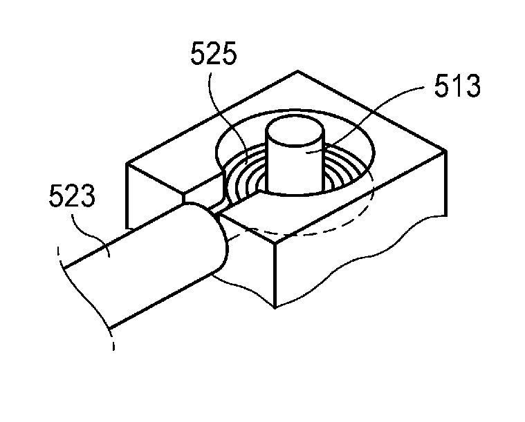
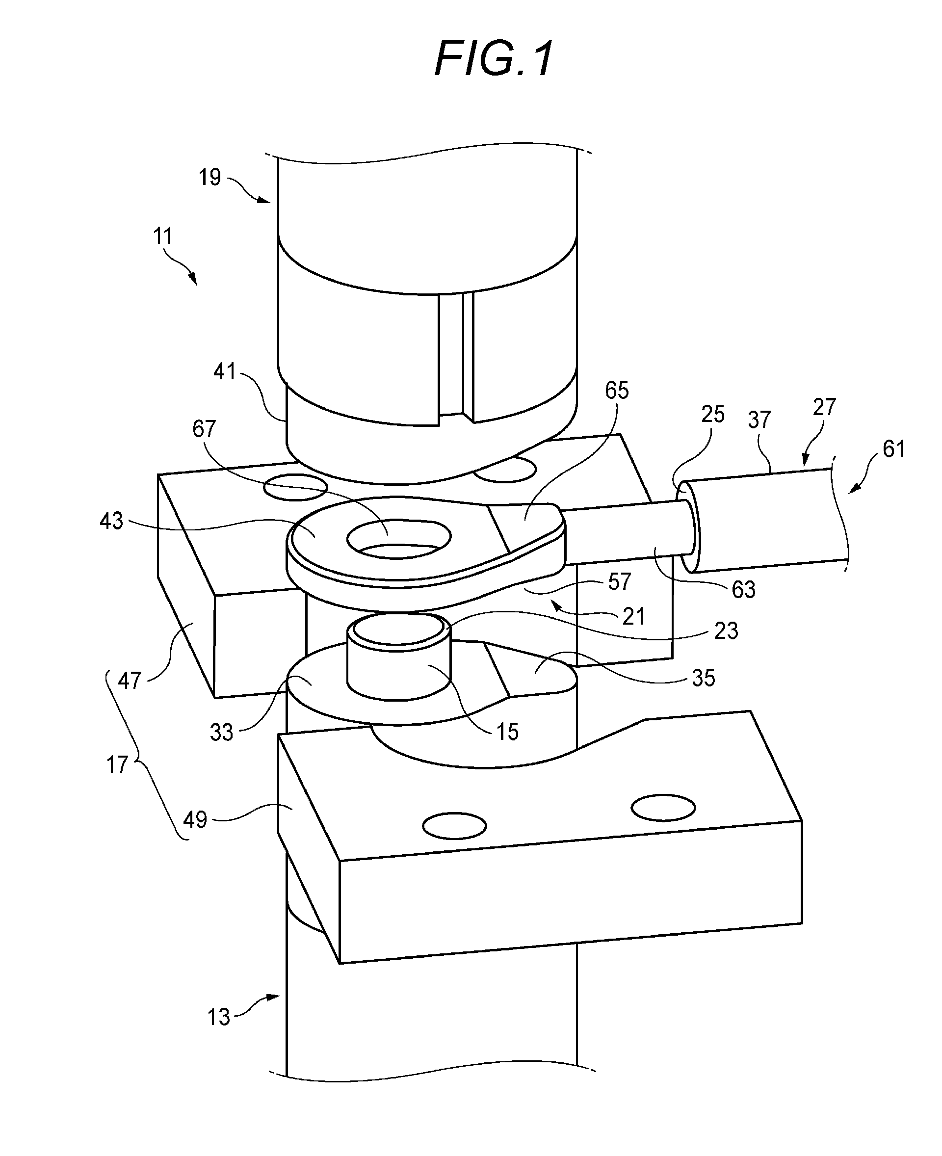
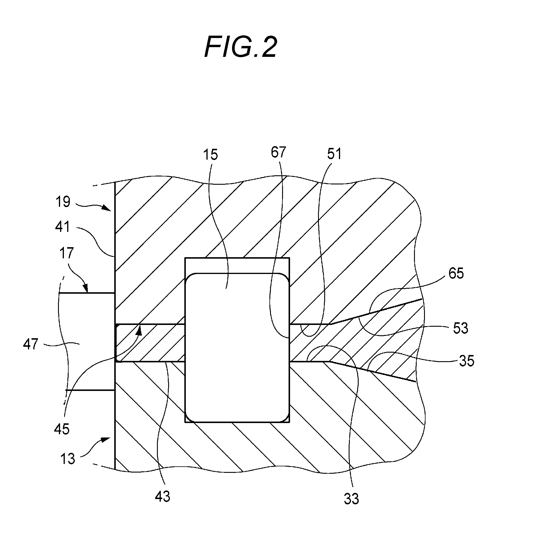
[0029]As shown in FIG. 1, a die 11 for a terminalized electric wire according to one exemplary embodiment of the present invention includes, as main components, a fixed side electrode 13 as a first electrode which is arranged in a lower part, a hole forming jig 15 which is allowed to stand upright on the fixed side electrode 13, an electric wire pressing jig 17 which surrounds a periphery of the fixed side electrode 13, a movable side electrode 19 as a second electrode which is opposed to and arranged in an upper part of the fixed side electrode 13, a conductor accommodation part 21 (see FIG. 5) provided in the electric wire pressing jig 17 and a clearance intruding bulge part 23 formed in the hole forming jig 15.

[0030]On the fixed side electrode (the first electrode) 13, an annular conductor 29 of an electric wire 27 in which a coating 25 is removed and an end side of a conductor 63 is superposed on a ro...


PUM

PropertyMeasurementUnit
Angleaaaaaaaaaa

Abstract

A die for a terminalized electric wire is provided with a first electrode, a hole forming jig, an electric wire pressing jig which surrounds a periphery of the first electrode, a second electrode and conductor accommodation parts. The conductor accommodation parts are recessed in molded inner wall surfaces at both sides of the electric wire pressing jig which holds a superposed configuration part in which the end side is superposed on the root side of the annular conductor in the vertical direction. A part of a molten conductor of the superposed configuration part flows into the conductor accommodation parts.

Description

CROSS REFERENCE TO RELATED APPLICATIONS[0001]This application claims priority from Japanese Patent Application No. 2015-057598 filed on Mar. 20, 2015, the entire contents of which are incorporated herein by reference.BACKGROUND OF THE INVENTION[0002]1. Field of the Invention[0003]The present invention relates to a die for a terminalized electric wire.[0004]2. Description of Related Art[0005]A molding electrode and a terminalized electric wire are known which can easily and assuredly change a core element wire of an electric wire to a terminal (for instance, see Patent Literature 1: JP-A-4-249875).[0006]As shown in FIG. 11A, the molding electrode 501 includes a female die press electrode 503 and a male die press electrode 505. The female die press electrode 503 has an electric wire accommodation groove 511 including an annular groove 507 and a cut out groove 509. In the center of the electric wire accommodation groove 511, a guide pin 513 for bending the electric wire is allowed to i...

Claims


Application Information

Patent Timeline
IPC IPC(8): H01R43/02B23K11/16B23K11/10
CPCH01R43/0214B23K11/16B23K11/10B23K11/0026B23K11/185B23K11/3009B23K2101/38B23K2103/10
Inventor KODA, YOSHITAKAMORI, SHIGEO
Owner YAZAKI CORP
Why Eureka
Try Eureka