Method and device for exhaust gas aftertreatment in an internal combustion engine

Inactive Publication Date: 2020-07-23
VOLKSWAGEN AG +1
View PDF0 Cites 3 Cited by
  • Summary
  • Abstract
  • Description
  • Claims
  • Application Information

AI Technical Summary

Benefits of technology

[0025]In this context, it is especially preferable for the air mass flow fed to the exhaust gas burner to be kept constant and for the adaptation of the air-fuel ratio of the exhaust gas burner to be effectuated by adapting the quantity of fuel that is injected into the combustion chamber of the exhaust gas burner. As a result, a very simple and precise pilot control of the air-fuel ratio of the exhaust gas burner is possible.
[0026]In an advantageous embodiment of the method, it is provided that, in a first operating state of the exhaust gas burner, the quantity of fuel of the exhaust gas burner is pilot-controlled in such a way that the exhaust gas burner is operated with a sub-stoichiometric air-fuel ratio and, in a second operating state, it is pilot-controlled in such a way that the exhaust gas burner is operated with a super-stoichiometric air-fuel ratio. A change between a sub-stoichiometric air-fuel ratio and a super-stoichiometric air-fuel ratio can ensure that unburned exhaust gas components, especially carbon monoxide, unburned hydrocarbons and hydrogen, are oxidized and nitrogen oxides are reduced. In this manner, the emissions during the heating phase of the three-way catalytic converter can be minimized.
[0027]In this context, it is especially preferred for the exhaust gas burner to be operated alternately with a sub-stoichiometric air-fuel ratio and with a super-stoichiometric air-fuel ratio. Thanks to this alternating operation, lambda blow-outs during the heating phase can be avoided, thereby ensuring an effective heating of the three-way catalytic converter and a simultaneous minimization of the tailpipe emissio

Problems solved by technology

This oxygen storage capacity causes any deviation of the lambda signal at the lamb

Method used


Image

  • Method and device for exhaust gas aftertreatment in an internal combustion engine
  • Method and device for exhaust gas aftertreatment in an internal combustion engine
  • Method and device for exhaust gas aftertreatment in an internal combustion engine

Examples


Embodiment Construction

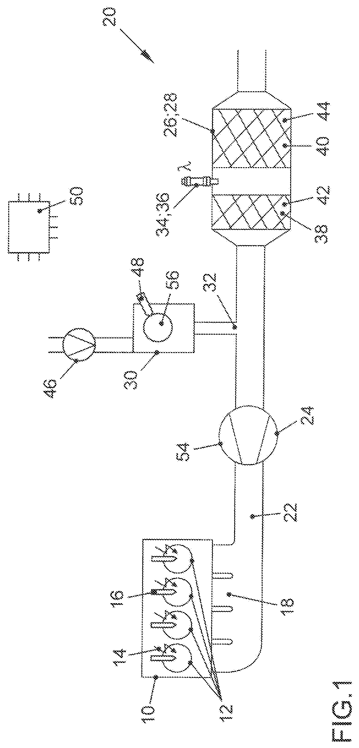
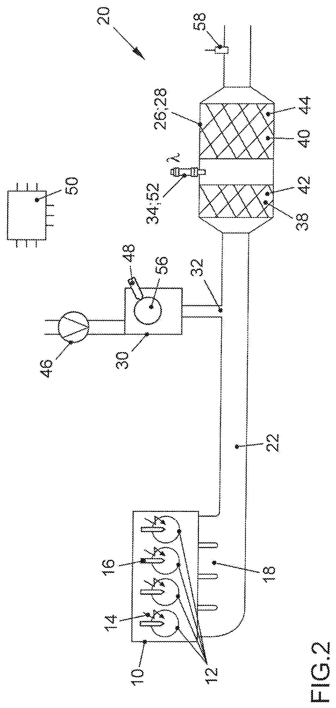
[0037]FIG. 1 shows an internal combustion engine 10 which has several combustion chambers 12 and whose outlet 18 is connected to an exhaust gas system 20. The internal combustion engine 10 is configured as a direct-injection gasoline engine. Each of the combustion chambers 12 has a spark plug 14 and a fuel injector 16 for purposes of injecting fuel into the appertaining combustion chamber 12 and igniting the fuel-air mixture. The exhaust gas system 20 comprises an exhaust gas channel 22 in which a turbine 24 of an exhaust gas turbocharger 54 and, downstream from the turbine 24, a three-way catalytic converter 26 are arranged in the direction in which exhaust gas from the internal combustion engine 10 flows through the exhaust gas channel. The three-way catalytic converter 26 is configured as a lambda probe catalytic converter 28. For this purpose, the three-way catalytic converter 26 has a first catalyst volume 38 and a second catalyst volume 40 arranged downstream from the first ca...


PUM


Abstract

A device for exhaust gas aftertreatment in an internal combustion engine can be connected to an outlet of the internal combustion engine. The device comprises an exhaust gas system with an exhaust gas channel in which a three-way catalytic converter is arranged, and an exhaust gas burner with which hot burner exhaust gases can be fed into the exhaust gas channel at a feed point upstream from the three-way catalytic converter. The three-way catalytic converter is configured as a lambda probe catalytic converter and comprises a first catalyst volume and a second catalyst volume, whereby a lambda probe is arranged downstream from the first catalyst volume and upstream from the second catalyst volume, whereby the first catalyst volume has a lower oxygen storage capacity than the second catalyst volume. A method for exhaust gas aftertreatment in an internal combustion engine has such an exhaust gas aftertreatment device.

Description

CROSS REFERENCE TO RELATED APPLICATIONS[0001]This application claims priority from German Patent Application No. 10 2019 101576.6, filed Jan. 23, 2019, which is incorporated by reference in its entirety.FIELD OF THE INVENTION[0002]The invention relates to a device for exhaust gas aftertreatment in an internal combustion engine as well as to a method for exhaust gas aftertreatment in an internal combustion engine.BACKGROUND OF THE INVENTION[0003]Current legislation on exhaust-gas emissions, which will become increasingly stringent in the future, makes high requirements regarding raw engine emissions and the exhaust gas aftertreatment in internal combustion engines. Moreover, the period of time immediately after a cold start of the internal combustion engine has acquired special significance in terms of the emissions since, during this phase, the exhaust gas aftertreatment components are supposed to be heated up to their operating temperature as quickly as possible in order to permit ...

Claims


Application Information

Patent Timeline
IPC IPC(8): F01N3/20F01N3/025F01N3/10
CPCF01N3/025F01N3/2033F01N3/101F01N2240/14F01N3/24F01N3/28F01N3/20F01N9/00F01N13/008F01N2340/06F01N2560/025F01N2900/1624F01N2900/1626F01N2900/1602F01N2900/1402Y02T10/40Y02T10/12F01N13/0093
Inventor BARON VON CEUMERN-LINDENSTJERNA, FALK-CHRISTIANPAUKNER, STEFANKAACK, MICHAELHEMMINGER, SEBASTIAN
Owner VOLKSWAGEN AG
Why Eureka
Try Eureka