Methods and systems for enhancing control of power plant generating units

a technology for enhancing control and power plant generating units, applied in adaptive control, process and machine control, instruments, etc., can solve the problems of affecting the actual output and efficiency of the power plant, increasing the cost of variable variables, and complex derivation methods

Active Publication Date: 2015-07-02
GENERAL ELECTRIC CO
View PDF7 Cites 56 Cited by
  • Summary
  • Abstract
  • Description
  • Claims
  • Application Information

AI Technical Summary

Problems solved by technology

In a combined-cycle power plant in which waste heat from a fuel burning generator is used to produce steam to power a supplemental steam turbine, an incremental variable cost curve may also be obtained with known techniques, but its derivation may be more complex.
However, the actual output and efficiency of a power plant is impacted by external factors, such as variable ambient conditions, that cannot be fully anticipated.
As will be appreciated, the complexity of such systems and the variability of operating conditions make it difficult to predict and control performance, which often result in inefficient operation.
Machine degradation that occurs over time is another difficult to quantify fact, which may have a significant effect on the performance of the generating units.
Hours-based life in a gas turbine may be prolonged by reducing firing temperature, but this reduces efficiency of the gas turbine, which increases cost of operation.
Conversely, increasing the tiring temperature increases efficiency, but shortens gas turbine life and increases maintenance and/or replacement costs.
Given the complexity of modern power plants, particularly those having multiple generating units, and the market within which it competes, power plant operators continued to struggle to maximize economic return.
For example, grid compliance and dispatch planning for a power plant is adversel...

Method used


Image

  • Methods and systems for enhancing control of power plant generating units
  • Methods and systems for enhancing control of power plant generating units
  • Methods and systems for enhancing control of power plant generating units

Examples


Embodiment Construction

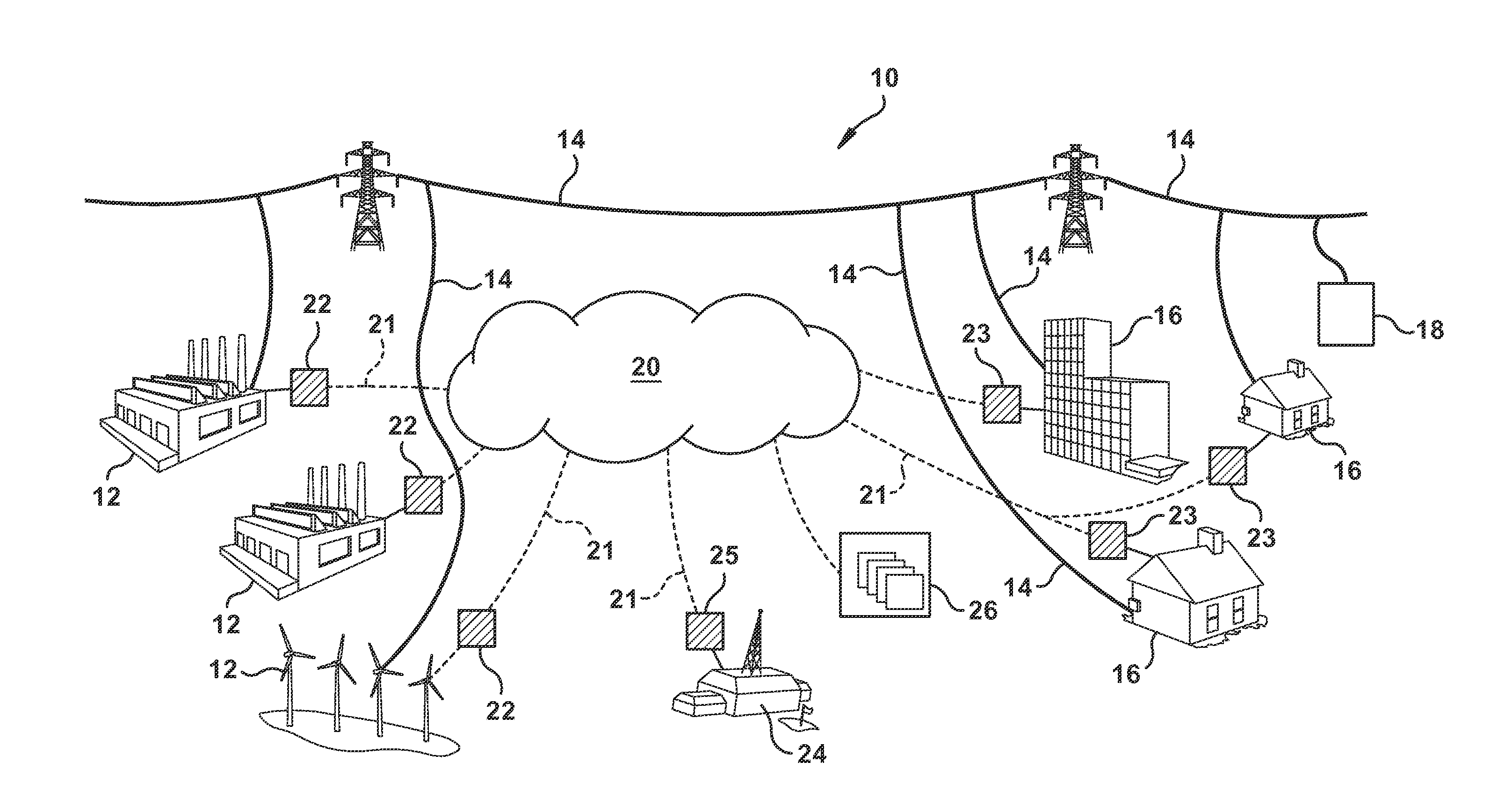
[0040]Example embodiments of the invention will be described more fully hereinafter with reference to the accompanying drawings, in which some, but not all embodiments are shown. Indeed, the invention may be embodied in many different forms and should not be construed as limited to the embodiments set forth herein; rather, these embodiments are provided so that this disclosure will satisfy applicable legal requirements. Like numbers may refer to like elements throughout.

[0041]According to aspects of the present invention, systems and methods are disclosed which may be used to optimize the performance of power systems, power plants, and / or thermal power generating units. In exemplary embodiments, this optimization includes an economic optimization by which an operator of a power plant decides between alternative modes of operation so to enhance profitability. Embodiments may be utilized within a particular power system so to provide a competitive edge in procuring advantageous econom...


PUM


Abstract

A control method for optimizing a turndown operation for a power plant having a plurality of generating units. The plurality of generating units each may include either an on-condition or an off-condition during a selected operating period. The method may include: defining competing operating modes, wherein the competing operating modes include different possible combinations regarding which of the plurality of generating units have the on-condition and which have the off-condition during the selected operating period; defining multiple cases for each of the competing operating modes, wherein the multiple cases include varying a value of an operating parameter; receiving performance objectives that include a cost function; receiving an ambient conditions forecast; for the multiple cases of the competing operating modes, simulating the turndown operation with a power plant model given the value of the operating parameter and the ambient conditions forecast; evaluating a simulation result pursuant to the cost function so to select therefrom a preferred case.

Description

CROSS-REFERENCE TO RELATED APPLICATIONS[0001]This application claims priority to U.S. Provisional patent application No. 61 / 922,555 entitled “TURBINE ENGINE AND PLANT OPERATIONAL FLEXIBILITY AND ECONOMIC OPTIMIZATION SYSTEMS AND PROCESSES RELATED THERETO” filed on Dec. 31, 2013, which provisional application is incorporated herein by reference in its entirety; this application claims the benefit of the provisional's filing date under 35 U.S.C. 119(e).BACKGROUND OF THE INVENTION[0002]The invention of the present application relates generally to power generation and, more particularly, to methods and systems related to the economic and performance optimization and / or enhancement of power plants having thermal generating units.[0003]In electric power systems, a number of participants or power plants generate electricity that is then distributed over common transmission lines to residential and commercial customers. As will be appreciated, thermal generating units, such as gas turbines,...

Claims


Application Information

Patent Timeline
IPC IPC(8): F01K13/02G05B13/04
CPCG05B13/04F01K13/02
Inventor WICHMANN, LISA ANNERACZYNSKI, CHRSTOPHER MICHAEL
Owner GENERAL ELECTRIC CO
Why Eureka
Try Eureka