System for Calibrating a Tribometer Test Foot

a technology of tribometer and test foot, which is applied in the field of tribometers, can solve the problems of not being able to reliably comply, not being able to reduce the permissible variations in test foot preparation, and still being, and being able to accurately assess the accuracy

Inactive Publication Date: 2015-07-02
WIDAS III GEORGE P
View PDF9 Cites 2 Cited by
  • Summary
  • Abstract
  • Description
  • Claims
  • Application Information

AI Technical Summary

Benefits of technology

[0005]The present invention provides a standardized test foot preparation device which makes it easy for users to achieve the required precision to comply with F2508. Henceforth, calibration tiles will have an assigned value based on the test foot calibration provided by the present invention. A user would not need not utilize the present invention if he or she could consistently produce reliable test foot preparation results on the certified calibration tile.

Problems solved by technology

These requirements substantially reduce the permissible variations in test foot preparation.
What was, and still is, more than sufficient to properly assess the accurate risk for a human slip and fall injury events is no longer enough to reliably comply with the F2508 criteria, the object of which is to assess the real world risk for a slip and fall injury event.

Method used


Image

  • System for Calibrating a Tribometer Test Foot
  • System for Calibrating a Tribometer Test Foot
  • System for Calibrating a Tribometer Test Foot

Examples


Embodiment Construction

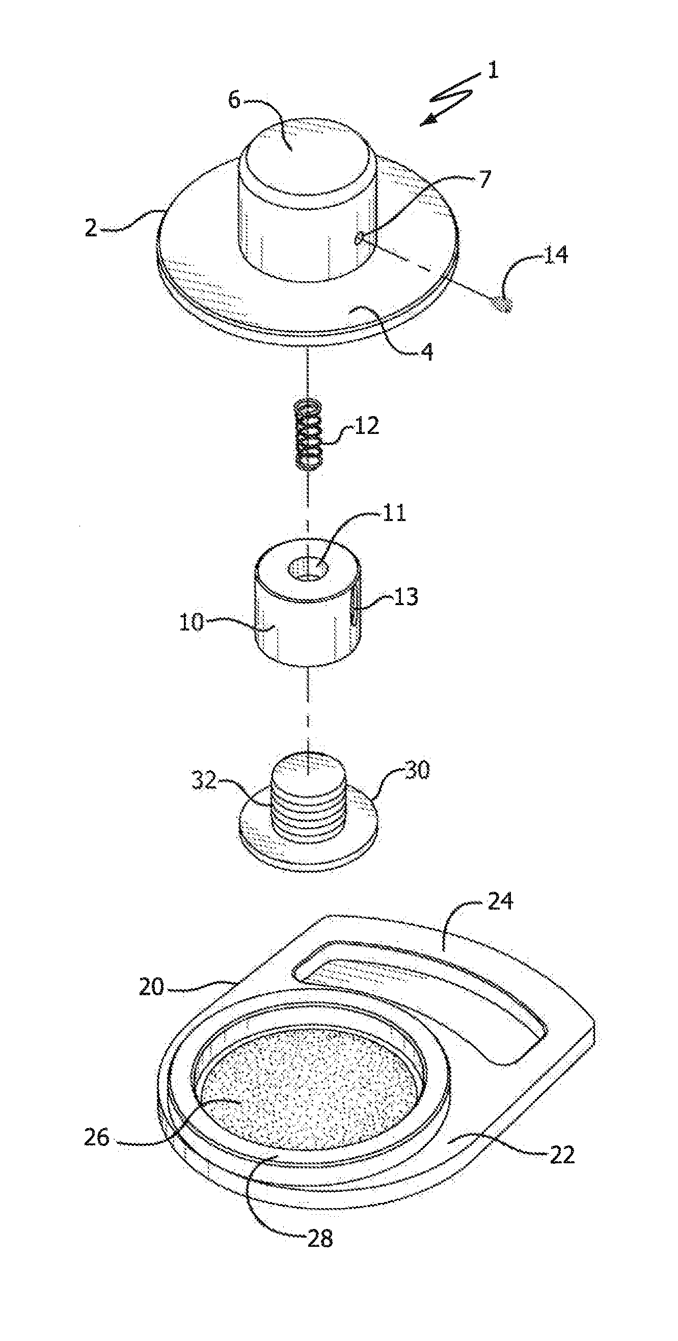
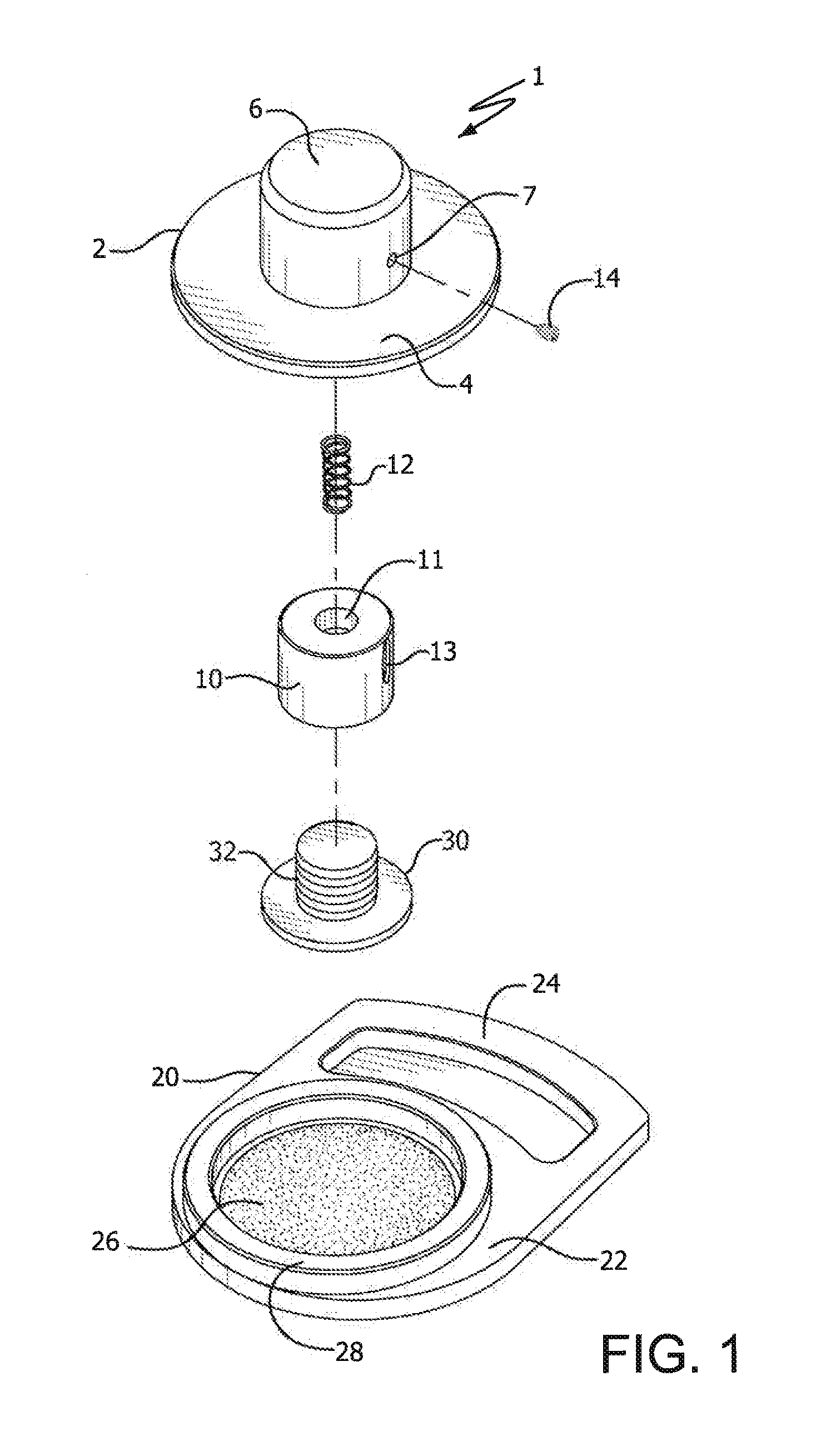
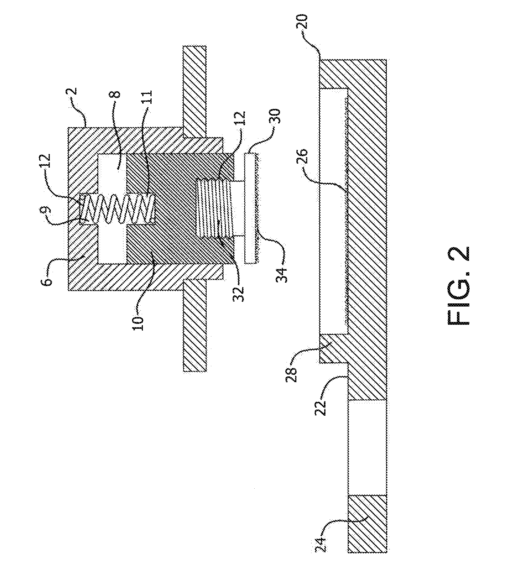
[0012]System 1 for calibrating a tribometer test foot comprises sander member 2 having base section 4 and top section 6 upstanding from the base section. Top section 6 has an open cavity 8 in which piston element 10 is located. A test foot connection means in the form of threaded test foot connection 12 is provided at the lower end of a test foot mounting element in the form of piston element 10. The piston element comprises vertical slot 13 aligned with tapped opening 7 through top section 6 of sander member 2. Tapping screw 14 extends through and is secured within opening 7 and into slot 13 in order to maintain piston element 10 in position within top section 6, so as to allow the piston to move vertically, i.e. up and down, within cavity 8 of the top section.

[0013]Spring 12 is positioned in cavity 8. The spring rests within indented space 11 of piston element 10 and extends into indent space 9 of top section 6 of sander member 2. Spring 12 is designed to biasedly maintain piston ...


PUM

PropertyMeasurementUnit
diameteraaaaaaaaaa
vertical movementaaaaaaaaaa
slip resistanceaaaaaaaaaa

Abstract

A system for the calibration of a tribometer test foot utilizes a uniquely designed sanding pad with a hard-back sandpaper surface, and a separate, independent sander member which has a top section with a test foot mounting element in the form of a piston having a threaded connection for securing the test foot. The sander member, with test foot attached, is configured to mate with the sanding pad to allow the test foot to be sanded to the required calibration. Calibration of the test foot is accomplished by pressing the sander member onto the sanding pad such that the test foot is compelled against the sandpaper surface of the sanding pad and rotating the sander member for the requisite sanding and thus accurate calibration of the test foot.

Description

FIELD OF THE INVENTION[0001]The present invention relates to tribometers for testing the slip resistance of various surfaces. More particularly, the present invention relates to improvements in accurately calibrating the test foot of a portable variable incidence tribometer, which measures the slip resistance of wet or oily, as well as dry surfaces, approximating the forces present during the walking process.BACKGROUND OF THE INVENTION[0002]A tribometer is a device used for measuring surface friction. Tribometric devices utilize various methods for determining the frictional force present when one surface is pulled or pushed across another under a predetermined pressure. These devices fall within three generally recognized categories: (1) dragsled, (2) articulated strut, and (3) pendulum type testers. There are numerous tribometric devices in each category which test the frictional threes between different dry surfaces.[0003]Various attempts have been made to provide devices which c...

Claims


Application Information

Patent Timeline
Patent Type & Authority Applications(United States)
IPC IPC(8): G01L25/00
CPCG01L25/00G01N19/02
Inventor WIDAS, III, GEORGE P.
Owner WIDAS III GEORGE P
Why Eureka
Try Eureka