
Three-dimensional image display apparatus, method, and program

a display apparatus and three-dimensional image technology, applied in the field of three-dimensional display apparatus and method, can solve the problems of not the different doctor who has added the information, and interfere with the observation of the three-dimensional visualization image, so as to achieve the effect of matching information and display conditions together, and being able to understand the intention of the doctor

Active Publication Date: 2015-07-02
FUJIFILM CORP
View PDF4 Cites 17 Cited by
  • Summary
  • Abstract
  • Description
  • Claims
  • Application Information

AI Technical Summary

Benefits of technology

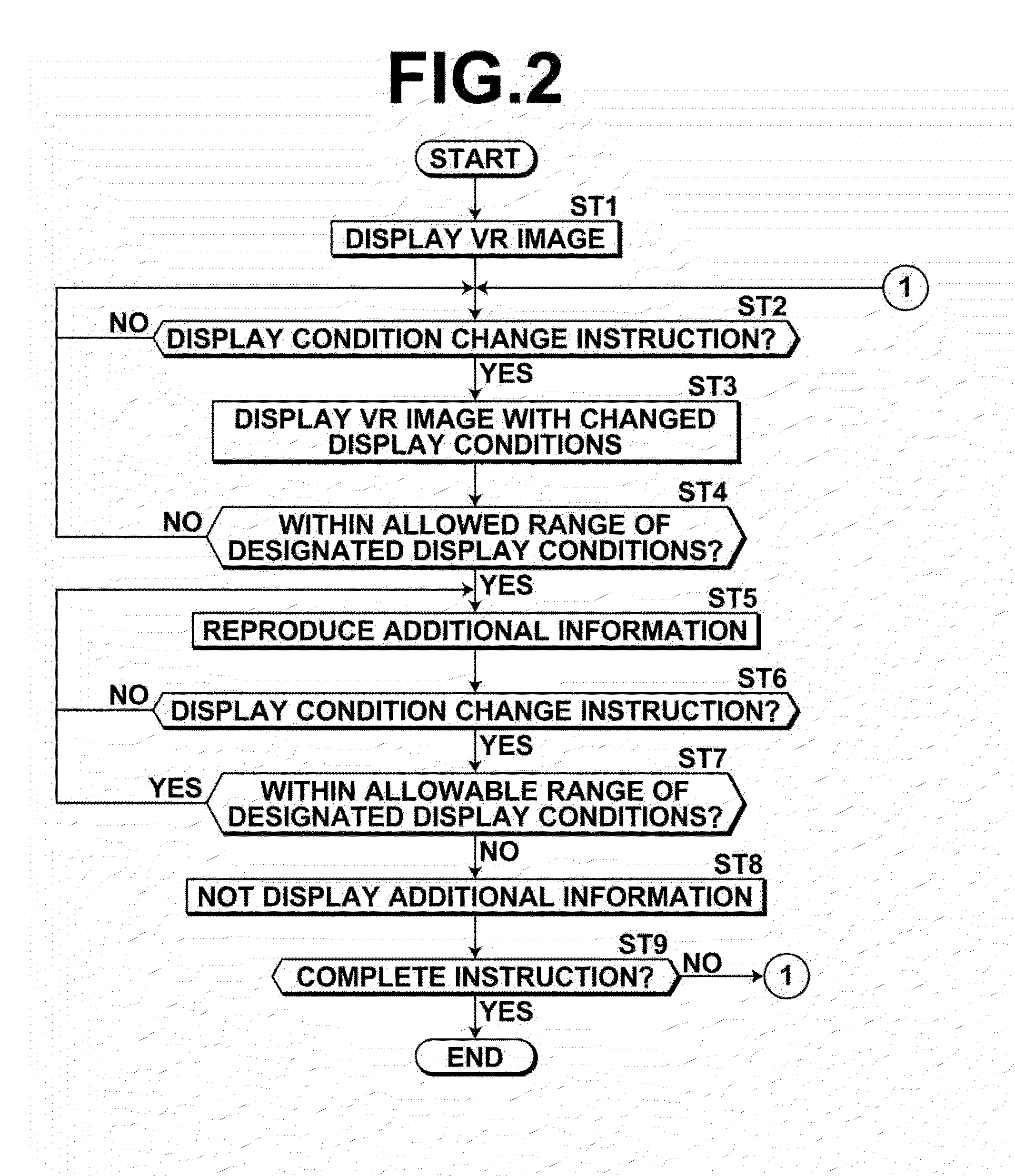
The present invention allows for setting limits on the display conditions for displaying three-dimensional visualization images. If the display conditions fall within the allowed limits, additional information related to the image will be enabled to be shown. This means that only necessary additional information will be displayed, and that unnecessary information will not interfere with the viewing of the visualization image. Additionally, the orientation of the image can be easily determined from the reproduced additional information, making it easier to understand and interpret the image as a whole.

Problems solved by technology

However, if a different doctor makes a final judgment, it is often the case that the intention of the doctor, who has added the information, cannot be understood by the different doctor.
In such a case, displaying all the information which has been added to the captured images will interfere with observation of the three-dimensional visualization image.
Moreover, it will not be possible to understand which information and which display conditions are matched together.
This technique cannot be applied in the case that display conditions are interactively changed.
In such techniques, there is a possibility that the meaning of displayed additional information cannot be understood if the orientation of a three-dimensional visualization image at the time that the additional information was added to the image differs from the orientation of the three-dimensional visualization image at the time that the additional information is displayed.

Method used


Image

  • Three-dimensional image display apparatus, method, and program
  • Three-dimensional image display apparatus, method, and program
  • Three-dimensional image display apparatus, method, and program

Examples


Embodiment Construction

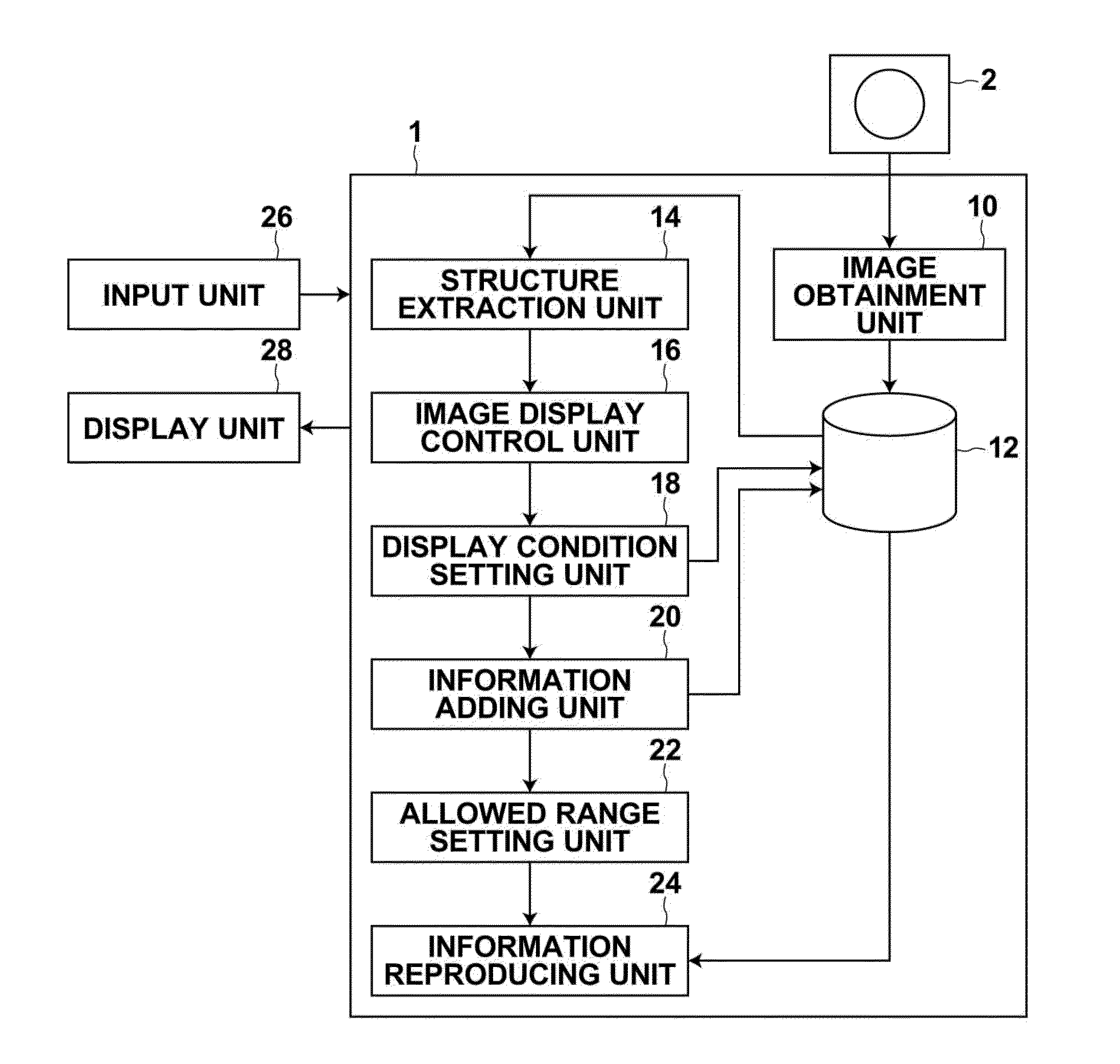
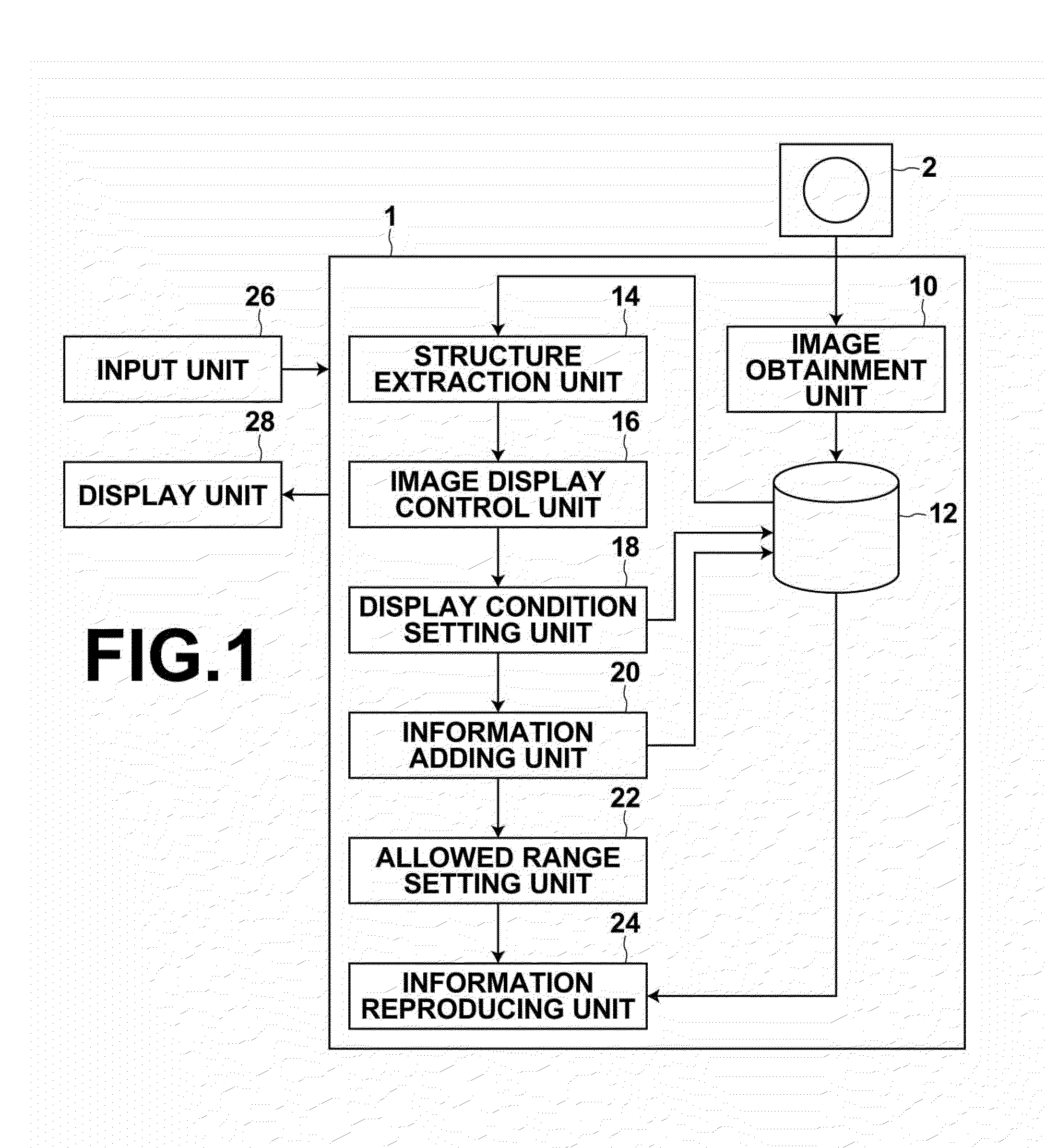
[0046]Hereinafter, the embodiment of the present invention will be described with reference to the drawings. FIG. 1 is a block diagram that schematically illustrates the configuration of a three-dimensional image display apparatus of an embodiment of the present invention. Note that the configuration of a three-dimensional image display apparatus 1 illustrated in FIG. 1 is realized by causing a three-dimensional image display program read into an auxiliary storage device to execute on a computer. This program is recorded in recording media such as CD-ROM's and the like or is distributed via a network such as the Internet to be installed in computers.

[0047]The three-dimensional image display apparatus 1 according to the present embodiment includes an image obtainment unit 10, a storage unit 12, a structure extraction unit 14, an image display control section 16, a display condition setting unit 18, an information adding unit 20, an allowable range setting unit 22, an information repr...


PUM


Abstract

A structure extraction unit extracts a heart region from a three-dimensional image of a chest, an image display control unit displays a volume rendering of the extracted heart region, an information adding unit adds additional information such as text and voice to a VR image displayed according to desired display conditions which include an image orientation. The display conditions when the additional information is added are stored with the additional information as designated display conditions. An allowable range setting unit sets a predetermined allowable range for the designated display conditions. During subsequent display of the VR image, an information reproducing unit enables the added information to be reproduced when display conditions are within the allowable range of the designated display conditions.

Description

CROSS-REFERENCE TO RELATED APPLICATIONS[0001]This application is a Continuation of PCT International Application No. PCT / JP2013 / 005327 filed on Sep. 9, 2013, which claims priority under 35 U.S.C. §119(a) to Japanese Patent Application No. 2012-201083 filed on Sep. 13, 2012. Each of the above applications is hereby expressly incorporated by reference, in its entirety, into the present application.BACKGROUND OF THE INVENTION[0002]1. Field of the Invention[0003]The present invention relates to a three-dimensional display apparatus and method for displaying three dimensional images which are composed of a plurality of tomographic images obtained by tomographic imaging of an object, and also relates to a program for causing a computer to execute the three-dimensional image display method.[0004]2. Description of the Related Art[0005]In recent years, three-dimensional images of high quality are increasingly used for diagnostic imaging, accompanying advances in medical instruments (for exam...

Claims


Application Information

Patent Timeline
IPC IPC(8): G06T15/08A61B19/00
CPCG06T15/08A61B19/5225G06T2207/30101A61B2019/524G06T2207/30048G06T2207/10081A61B2019/5295G06T2207/30061A61B6/463A61B6/466A61B6/503G06T11/00G06T19/006G06T2210/41
Inventor MASUMOTO, JUN
Owner FUJIFILM CORP
Learn More