Method and apparatus to project image on retina at various focal depths utilizing flexible substrate containing optical array

a flexible substrate and optical array technology, applied in the field of three-dimensional visual perception technology, can solve the problems of prior art's 3d vision being obvious from reality, unable to re-produce life, and unable to allow viewers to view all objects within the same scene clearly

Inactive Publication Date: 2015-07-02
ZHOU YUCHEN
View PDF4 Cites 39 Cited by
  • Summary
  • Abstract
  • Description
  • Claims
  • Application Information

AI Technical Summary

Benefits of technology

[0013]This method provides the viewer the ability to view the objects of interest in focus at will, while not requiring the viewer's effort to actively participate to achieve such re-focus task.
[0014]This invention helps achieve 3D vision that most closely simulates real-life viewing experience, and can give the impression of viewing a real-life scene where viewer can focus on objects of interest with pure intention.

Problems solved by technology

A fundamental drawback of all existing stereo-vision techniques and 3D movie techniques in the attempt to simulate real-life viewing experience is that when the object images are captured from two different viewing angles, objects 391 and 392 that are focused upon will show up as focused objects when projected on screen.
The existing prior art techniques do not allow viewer to view all objects within same scene clearly and does not have a method to bring objects into focus at viewer's own discretion.
This limitation makes 3D vision of prior art an obvious deviation from reality.
Prior art is limited in the ability to re-produce the life-like stereo-vision viewing experience.

Method used


Image

  • Method and apparatus to project image on retina at various focal depths utilizing flexible substrate containing optical array
  • Method and apparatus to project image on retina at various focal depths utilizing flexible substrate containing optical array
  • Method and apparatus to project image on retina at various focal depths utilizing flexible substrate containing optical array

Examples


first embodiment

[0139]Now, coming back to the For the Step 103 of calculating the desired focus depth (Step 103) and retrieving image (Step 104), a computing system is used to obtain information of viewer's eye-lens, eyeball or brainwave pattern change from the sensors sensing such information from the viewer, and calculate the desired re-focus depth of the viewer about the image currently shown to the viewer. For brain-pattern recognition of viewer's re-focus intention, a brain-wave pattern database also provides information to the computing system to compare to the received brain pattern. Calculation of intended focus depth in Step 103 can be computed by the eye-lens, or together with eye-ball change, information obtained in Step 102, and optionally together with the image currently being displayed to the viewer. An image capturing device, for example a camera, can be in close proximity to the viewer's eyes to capture the scene that the viewer is currently being exposed to, wherein the eye-lens ...

second embodiment

[0151]FIG. 20 is a schematic flow diagram illustrating the second embodiment wherein eye-lens and eye-ball sensing of eye-information are used. All other steps, descriptions and procedures are same as in FIG. 18 case, except Step-1001 and Step-1002 are removed, wherein 205 recording media or recorded image database already exists and contains images simultaneously recorded from the same scene with different focus depth.

[0152]FIG. 21 is a schematic flow diagram illustrating the second embodiment wherein brain-wave pattern sensing of re-focus intention are used. All other steps, descriptions and procedures are same as in FIG. 19 case, except Step-1001 and Step-1002 are removed, wherein 215 recording media or recorded image database already exists and contains images simultaneously recorded from the same scene with different focus depth.

[0153]The third embodiment of the current invention is for enhanced human vision. The method according to the third embodiment includes the steps of: (...

third embodiment

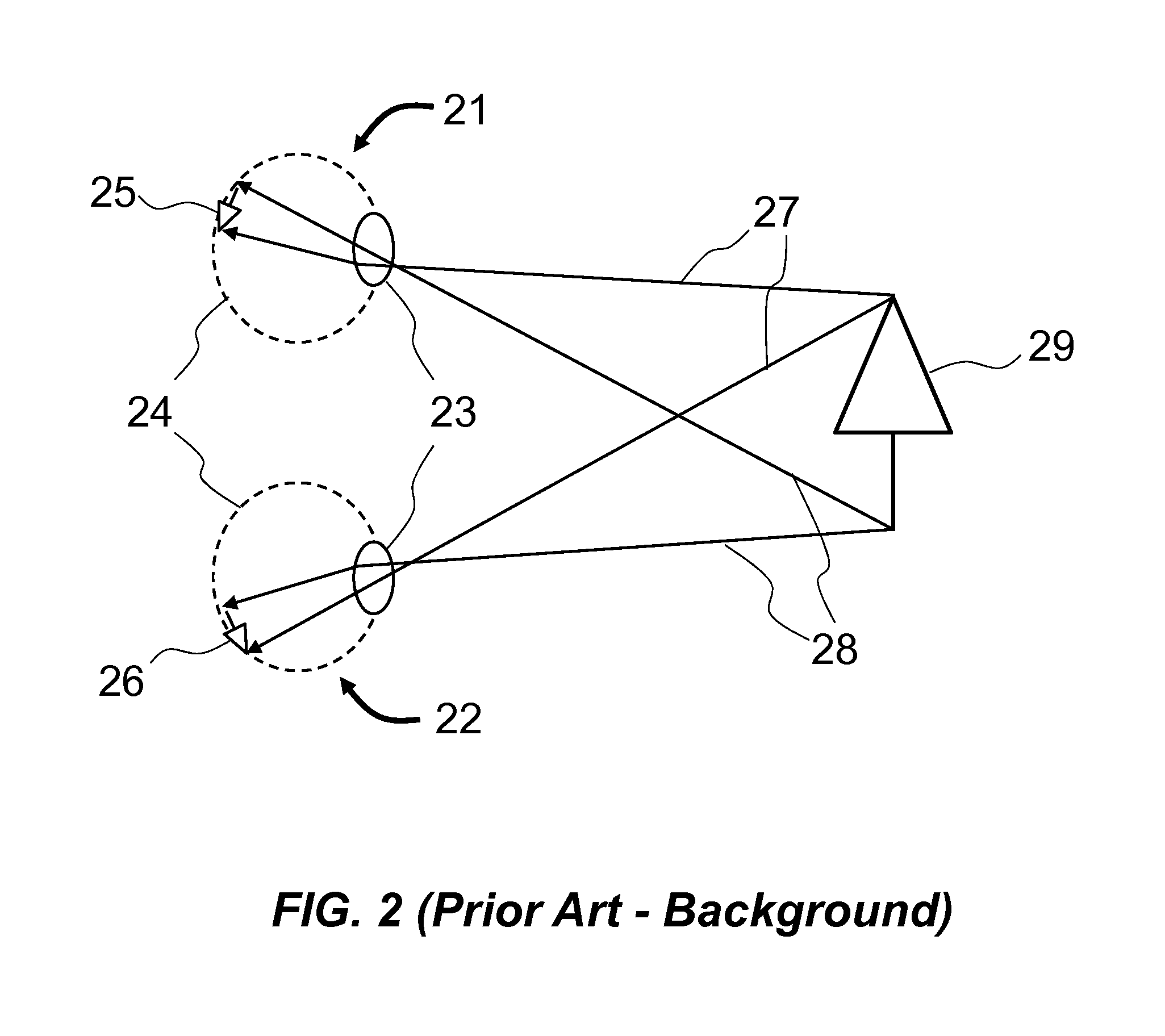
[0157]FIG. 22 is a schematic flow diagram illustrating the third embodiment wherein eye-lens and eye-ball sensing of eye-information are used, including: (Step-3001) A scene 221 of objects is recorded by a recording device 223 having a focus depth adjustment component 224 as in 222; (Step-3002) A sensor 229 is positioned in proximity to the viewer's eye 220 and collects the re-focusing information or data from viewer's eye 220; (Step-3003) The said re-focusing data is transmitted as in 2293 to the device 228 for computing desired focus depth of the viewer; (Step-3004) The device 228 computes the desired focus depth of the viewer and determines the adjustment needed in said focus depth adjustment component 224; (Step-3005) The device 228 sends request to focus depth adjustment component 224 to adjust to desired focus depth of the viewer as in 2294; (Step-3006) The recording device 223 records image of current scene 221 of objects with adjusted focus depth adjustment component 224 and...


PUM


Abstract

The current invention relates to the method to achieve artificial vision with using flexible substrate based light emitting arrays, or optical passage arrays, to project image upon the retina of a human eye. Further, it relates to the method to detect the real-time focal length change of the eye-lens and modify the flexible substrate curvature and distance from the eye to vary global angle configurations of light beams that go into the eye to produce images on the retina at various focus depth of the eye to achieve re-focusable artificial vision.

Description

CROSS-REFERENCE TO RELATED APPLICATIONS[0001]The present application is a Continuation-In-Part of the commonly assigned application bearing Ser. No. 14 / 162,758, filed on Jan. 24, 2014, by Yuchen ZHOU, and entitled “METHOD AND APPARATUS TO PRODUCE RE-FOCUSABLE VISION WITH DETECTING RE-FOCUSING EVENT FROM HUMAN EYE,” which claims the benefit of the provisional application bearing Ser. No. 61 / 756,443, filed on Jan. 24, 2013, by Yuchen ZHOU, and entitled “Re-focusable stereo vision,” as well as the benefit of the provisional application bearing Ser. No. 61 / 771,091, filed on Mar. 1, 2013, by Yuchen ZHOU, and entitled “RE-FOCUSABLE STEREO VISION.”BACKGROUND[0002]The current invention generally relates to three-dimensional visual perception technology and more particularly to a system and method for realizing real-time re-focusable stereo vision.[0003]Stereo vision, or stereoscopic vision, better known as 3D vision, realizes three-dimensional visual perception of an object by recording the...

Claims


Application Information

Patent Timeline
Patent Type & Authority Applications(United States)
IPC IPC(8): H04N13/04H04N13/00H04N13/122
CPCH04N13/0484H04N13/0014H04N13/0418G06F3/011G06F3/015G06F3/017G06F3/04847G06F3/04842G06F3/013G02B26/0833H04N13/161H04N13/207H04N13/243H04N13/341H04N13/383G02B27/0093G02B27/0172G02B2027/0178H04N13/344H04N13/122H04N13/128H04N13/156H04N13/25H04N13/271H04N13/322H04N13/332G02B26/0825
Inventor ZHOU, YUCHEN
Owner ZHOU YUCHEN
Why Eureka
Try Eureka