

Intraocular lens
a technology of intraocular lens and lens body, applied in the field of intraocular lens, can solve the problems of inability to ensure that the effect of visual correction for both farsightedness and nearsightedness is obtained, the pinhole portion relative to the eyeball is unstable, and the contact lens that is attached to the cornea and used in an unfixed condition moves. achieve the effect of stably and reliably
- Summary
- Abstract
- Description
- Claims
- Application Information
AI Technical Summary
Benefits of technology
Problems solved by technology
Method used
Image

Examples
first embodiment
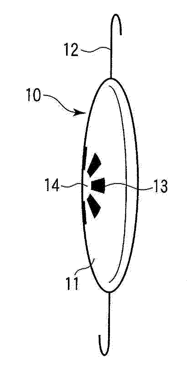
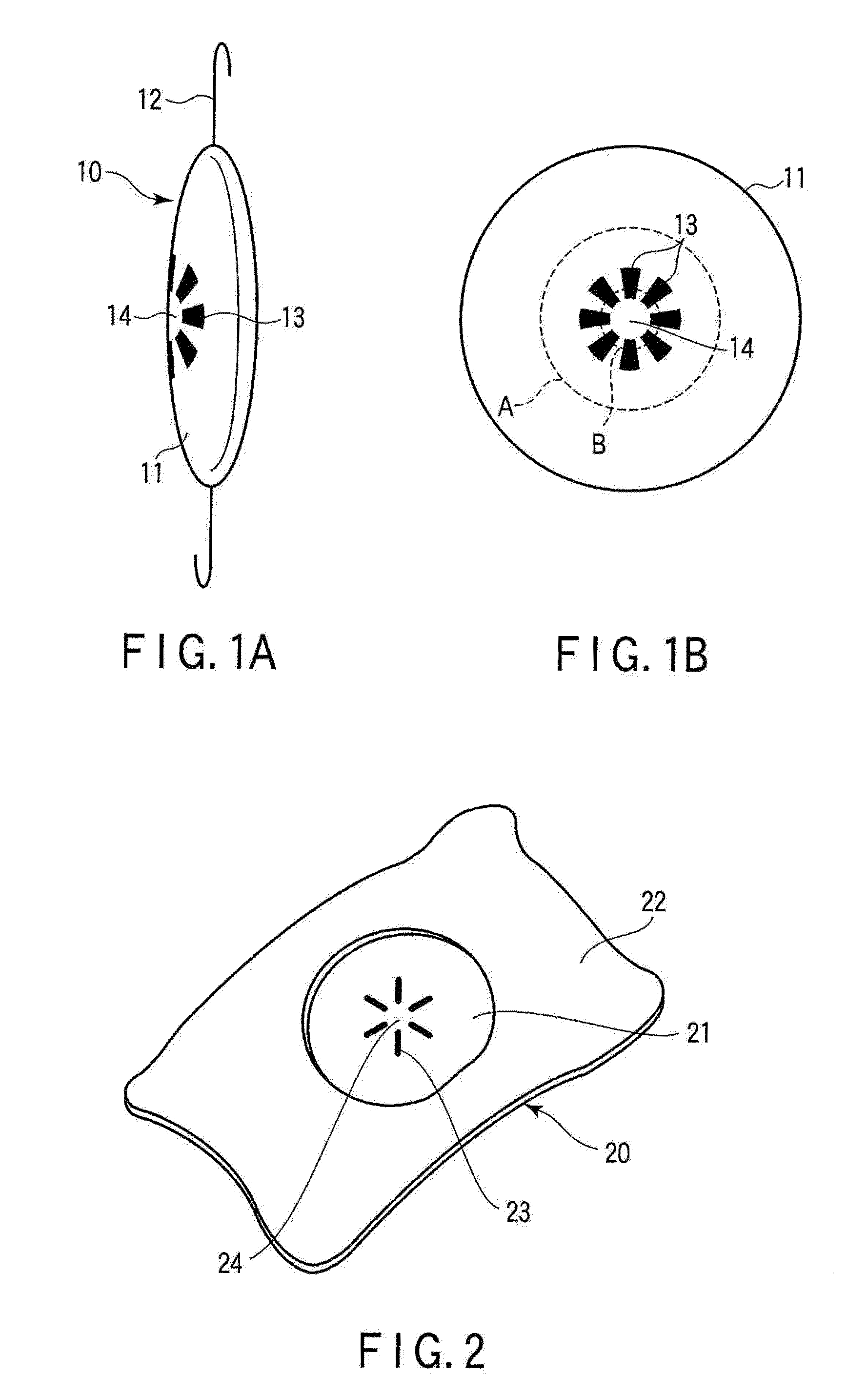
[0028]FIG. 1A is a perspective view schematically showing an intraocular lens according to a first embodiment of the present invention. As shown in FIG. 1A, an intraocular lens 10 includes an intraocular lens body 11 made of a transparent material, and a holder 12 for holding and fixing the intraocular lens body 11 in an eyeball. In the intraocular lens body 11, a limitative pattern for limiting part of an optical path (light input) is partly formed, so that an optical pupil 14 for providing a pinhole effect is formed in the front center. As described later, considering a practically proper aperture ratio, it is possible to obtain various shapes of the limitative pattern, various ranges of optical path limitation by the limitative pattern, and various amounts of light input limitation by the limitative pattern.
[0029]FIG. 1B is a front view of the intraocular lens body shown in FIG. 1A. In the intraocular lens body 11, the limitative pattern (a light shielding pattern 13 in this exam...
second embodiment
[0037]FIG. 2 is a perspective view schematically showing an intraocular lens according to a second embodiment of the present invention. The intraocular lens according to the second embodiment is a contact lens for intraocular attachment, which is inserted into an eyeball, e.g., of a human being, attached (implanted) in front of a crystalline lens in the eyeball, and used in an intraocularly fixed condition. The intraocular lens 20 includes a lens body portion 21 made of a transparent material and attached in front of the crystalline lens, and a peripheral portion 22 surrounding the lens body portion 21. The lens body portion 21 and the peripheral portion 22 may be integrally formed. The lens body portion 21 and the peripheral portion 22 may be also formed as separated members and then joined to each other. The peripheral portion 22 functions as a holder for holding and fixing the lens body portion 21 in the eyeball.
[0038]In the lens body portion 21, a limitative pattern (a light shi...
example 1
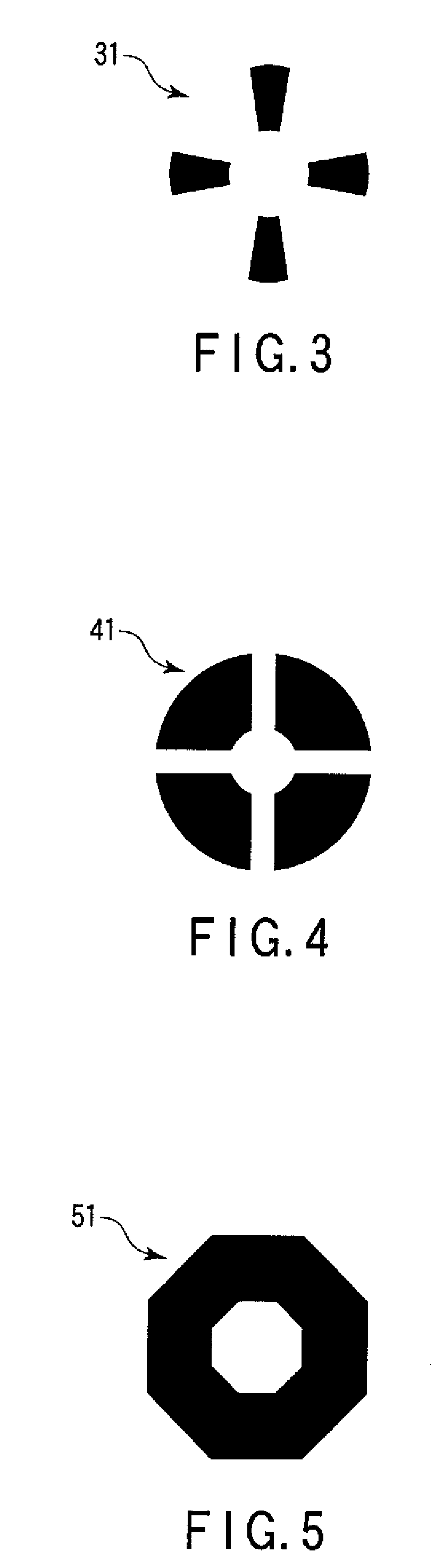
[0046]FIG. 1B is a front view schematically showing a light shielding pattern in Example 1 of the present invention. This light shielding pattern 13 has a plurality of (e.g., eight) thin radial patterns discontinuously formed at a small pitch in a circular ring region at the front peripheral center of an intraocular lens body 11. The overall size (in this example, the diameter of the circular ring region where the light shielding pattern is formed) of the light shielding pattern 13 is set at a proper value ranging from 5 mm to 6 mm, which is smaller than a size of the pupil formed by the iris of the eyeball in night vision. An optical pupil 14 in the center of the light shielding pattern is substantially circular, and its diameter is set at a proper value ranging from 0.2 mm to 2.5 mm, which is smaller than a size of the pupil formed by the iris of the eyeball in clear vision.
[0047]According to Example 1, the size of the light shielding pattern 13 is smaller than the size of the pup...
PUM
 Abstract
Description
Claims
Application Information