
Extended Depth Field Optics With Variable Pupil Diameter

Active Publication Date: 2013-11-21
UNIV OF COLORADO THE REGENTS OF
View PDF4 Cites 24 Cited by
  • Summary
  • Abstract
  • Description
  • Claims
  • Application Information

AI Technical Summary

Benefits of technology

The present invention provides a way to make human eyes see more clearly. By making changes to the optical properties of the eye, such as the thickness of the cornea or the shape of the lens, the invention creates an extended depth of field, meaning the eye can focus on objects at different distances. This improves the overall clarity of the image and reduces blurring. The invention uses a coded image that is decoded by the brain, resulting in a sharp image over a larger depth of field. This extended depth of field is important for correcting refocusing difficulty and chromatic aberration, and can provide a better overall image quality.

Problems solved by technology

In the human eye, it is well known that the accommodation of the lens (or refocusing ability) decreases with age, resulting in an inability to focus over the usual range of distances.
Then, there is presbyopia, which is when the lens hardens with age, and makes it difficult to focus up close.
The major disadvantage of this approach is that when an object is in between the ranges where one of the foci provides an in-focus image, the brain has difficulty in choosing which of the blurry images to pick.
This causes headaches and difficulty in seeing.
Another major disadvantage of this technique is that if the two images are not aligned (as occurs when the lens is not centered, a frequent occurrence with contact lenses) the images do not line up and the out-of-focus image is apparent.
Another disadvantage is loss of contrast.
The loss of contrast is even worse when the object is located between a reading distance and a very long distance; examples include the distance to a computer screen, a television set, or music on a stand.
This approach works for many people, but the inability to fuse images that are not both focused has made this solution unusable for many others because the user sees two misregistered images.
Again, problems occur if neither image is in focus.
The problem that some people have is getting used to the distortion.
Modeling suggests that the performance of these two products is quite uneven over both distance and pupil size.

Method used


Image

  • Extended Depth Field Optics With Variable Pupil Diameter
  • Extended Depth Field Optics With Variable Pupil Diameter
  • Extended Depth Field Optics With Variable Pupil Diameter

Examples


first embodiment

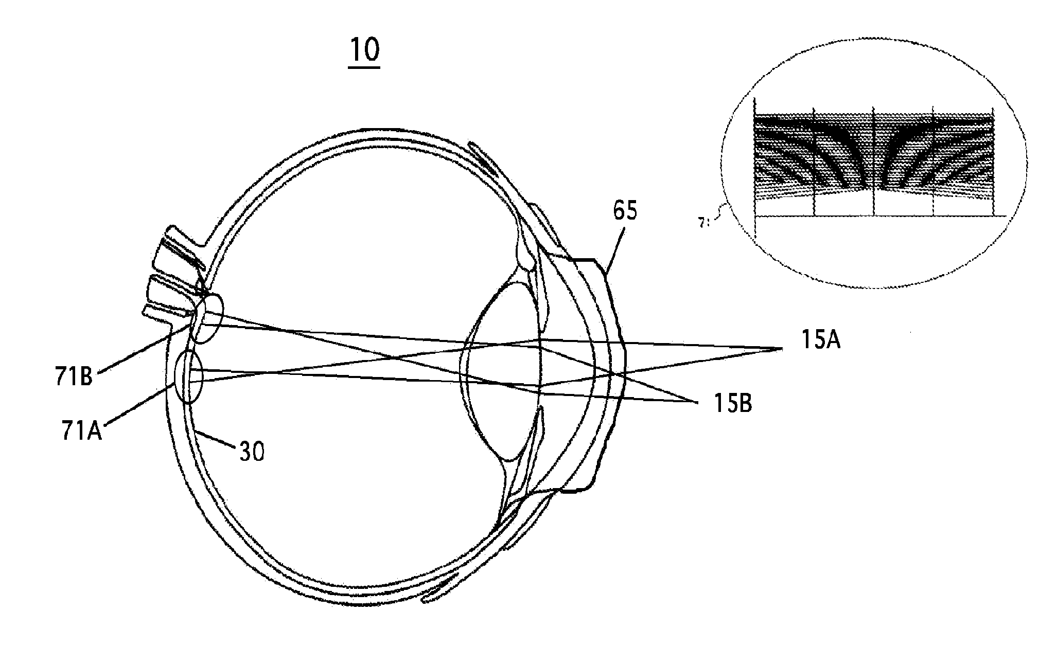
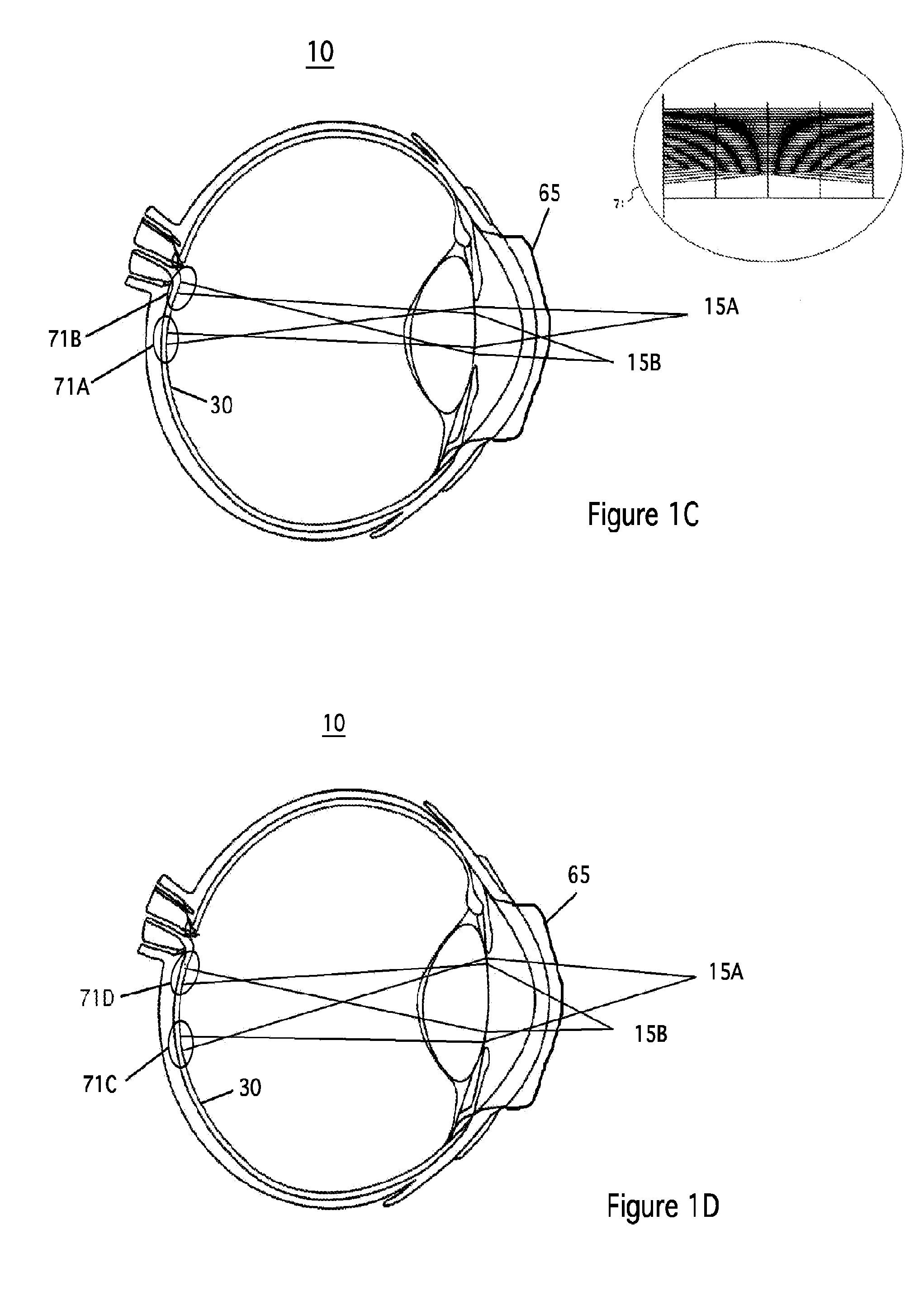
[0035]FIG. 2 is an isometric view of an extended depth of field (EDOF) contact lens 65 according to the present invention. The profile of lens 65 comprises concentric, circularly symmetric rings of varying depth. The structure of the lens is chosen such that the optical transfer function remains relatively constant over a range of pupil diameters, as well as object distances. The circularly symmetric structure is advantageous in that a user does not have to worry about contact lenses rotating. It also simplifies manufacturing.

second embodiment

[0036]FIG. 3 is a plot showing the profile of an EDOF optic according to the present invention. The x-axis has been normalized. In general, a contact lens will have a diameter on the order of 6 mm.

[0037]FIG. 4 is a plot showing a modulation transfer function of a normal human eye focusing on an object one meter away. The human eye focuses by changing the shape of its lens 28 (see FIG. 1, Prior Art). The x-axis of the plot of FIG. 4 is the focus shift away from the ideal focus of lens 28. The focus shift of the eye in order to focus at infinity is shown (1 diopter, or approximately 0.38 mm) and the focus shift to focus at 0.5 mm is also shown (1 diopter, or approximately −0.36 mm). Objects can't be further away than infinity, but the eye can shift focus past the equivalent focus shift, so the plot extends further than where “object at infinity” is indicated. Note that the MTF is far from uniform, and includes zeroes, albeit outside the relevant focus shift range. The peak of the MTF ...


PUM


Abstract

Apparatus and methods to increase the depth of field in human vision in order to correct for loss in refocusing ability. Optics variations, such as changes in thickness, shape, or index of refraction of contact lenses, intraocular implants, or the shape of the cornea or eye lens, affect the phase, or wavefront, of the light perceived by the eye. The optics variations are chosen such that the resulting optical transfer function remains relatively constant over a desired range of object distances and pupil diameters.

Description

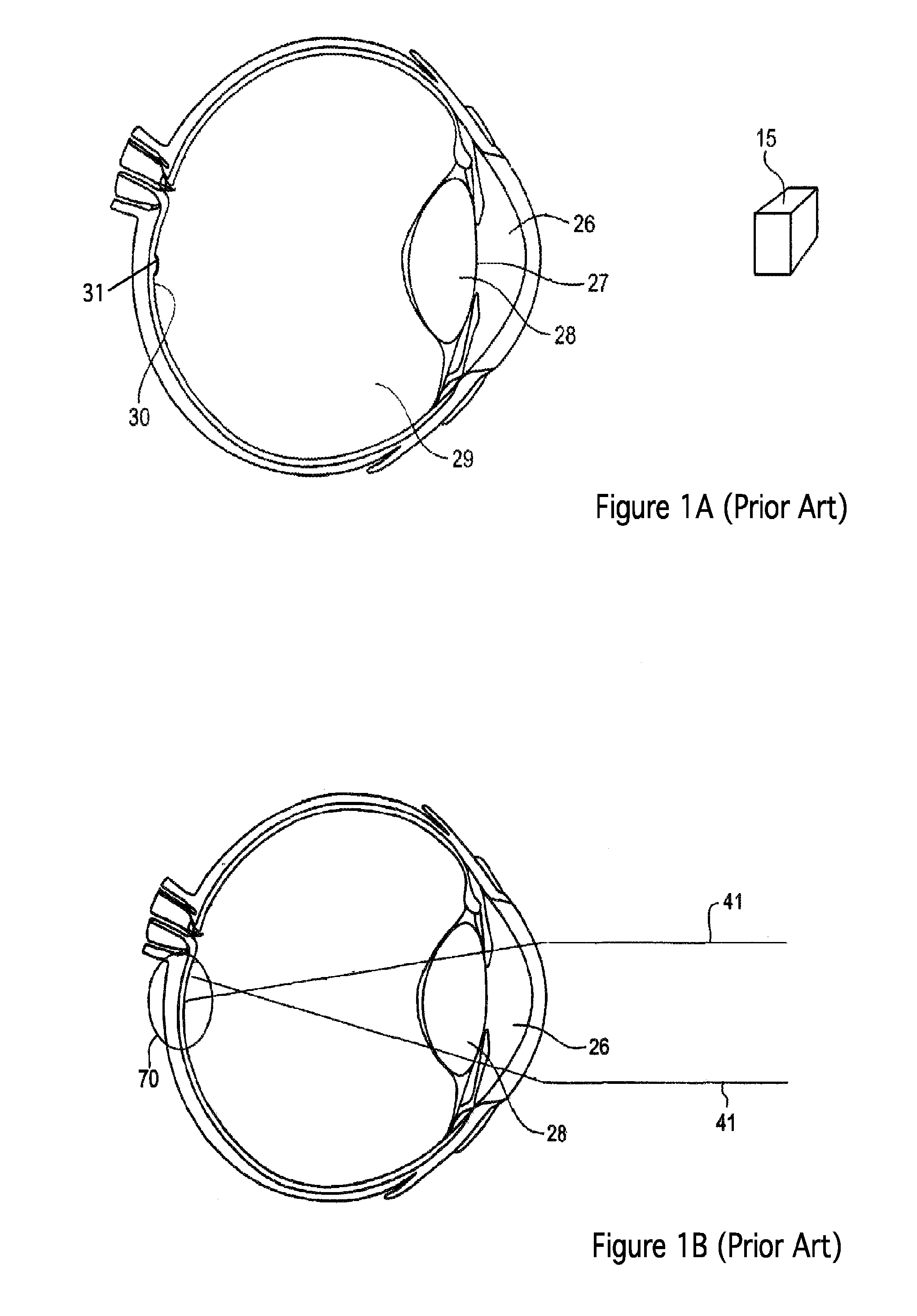
BACKGROUND OF THE INVENTION[0001]1. Field of the Invention[0002]The present invention relates to extending depth of field in human vision by causing the response to be largely independent of both distance to an object and pupil diameter. In particular, the present invention causes the optical transfer function of an optical element to remain relatively constant over a range of pupil diameters and distances.[0003]2. Description of the Related Art[0004]In the human eye, it is well known that the accommodation of the lens (or refocusing ability) decreases with age, resulting in an inability to focus over the usual range of distances. In addition, individuals with wrinkled retina have poor or no vision in a portion of the field of view. FIG. 1A (Prior Art) shows a human eye 10 with cornea 26, pupil 27, lens 28, vitreous humor 29, and retina 30 having a retina wrinkle or macular pucker 31.[0005]Myopia, nearsightedness, is when light 41 from a distant object produces a focus in front of t...

Claims


Application Information

Patent Timeline
IPC IPC(8): A61F2/16G02C7/04G02B27/00G02C7/02
CPCA61F2/16G02C7/022G02C7/04G02B27/0075A61F2/14G02B21/02G02B23/00G02B27/0025G02C7/042
Inventor CATHEY, JR., W. THOMASCORMACK, ROBERT H.
Owner UNIV OF COLORADO THE REGENTS OF
Learn More