System and method for measuring tilt in the crystalline lens for laser phaco fragmentation

a technology of crystalline lens and laser phaco fragmentation, which is applied in the field of three-dimensional images of cornea and eye lens, can solve the problems of all incisions missing the lens capsule and cutting instead, increasing the risk of anterior capsule tear, and obstructing or interfering with the laser

Active Publication Date: 2012-12-27
LENSAR LLC
View PDF4 Cites 26 Cited by
  • Summary
  • Abstract
  • Description
  • Claims
  • Application Information

AI Technical Summary

Benefits of technology

[0021]One or more aspects of the present invention allow for compensa

Problems solved by technology

The formation of bubbles under the capsule can interfere with the laser cut and result in capsulotomies that are not completely cut and have residual tissue bridges between the capsulotomy “button” (circular region of anterior capsule which is removed) and the remaining lens capsule which must be manually torn.
Anterior chamber bubbles can obstruct or interfere with the laser as the laser traverses the bubbles to cut parts of the cornea or lens in later parts of the laser procedure.
However, the requirement for small edge heights must be balanced against the risk that some or all of the incisions will miss the lens capsule and cut instead in the lens fibrous body or in the anterior chamber due to slight errors in the measurement of the lens capsule position or the positioning of the laser beam when making the incisions.
Obviously, missing all or part of the lens capsule necessitates later manual tearing of some or all of the capsule—which negates some or all of the advantage of using the laser itself and which may also increase the risk of an anterior capsule tear when the surgeon tries to connect two parts of a laser cut with a manual tear to complete the capsulotomy.
While the arcuate incisions must cut deep into the eye (typically 90% of the 500-700 μm thickness of the cornea), it is undesirable to cut all the way through the cornea.
With a poorly centered IOL, the capsular edge may be partially on and partially off the IOL's optic and the fibrosis will tend to pull one side of the IOL forward more than the other side, causing the lens to tilt with a resulting increase in aberrations in the images the IOL forms on the retina.
Although the foregoing IOL centration method is widely used, it has the disadvantage that it frequently results in a shift in the optic axis of the eye following cataract surgery.
This method forces the surgeon to interrupt the surgery to perform the time c

Method used


Image

  • System and method for measuring tilt in the crystalline lens for laser phaco fragmentation
  • System and method for measuring tilt in the crystalline lens for laser phaco fragmentation
  • System and method for measuring tilt in the crystalline lens for laser phaco fragmentation

Examples


Embodiment Construction

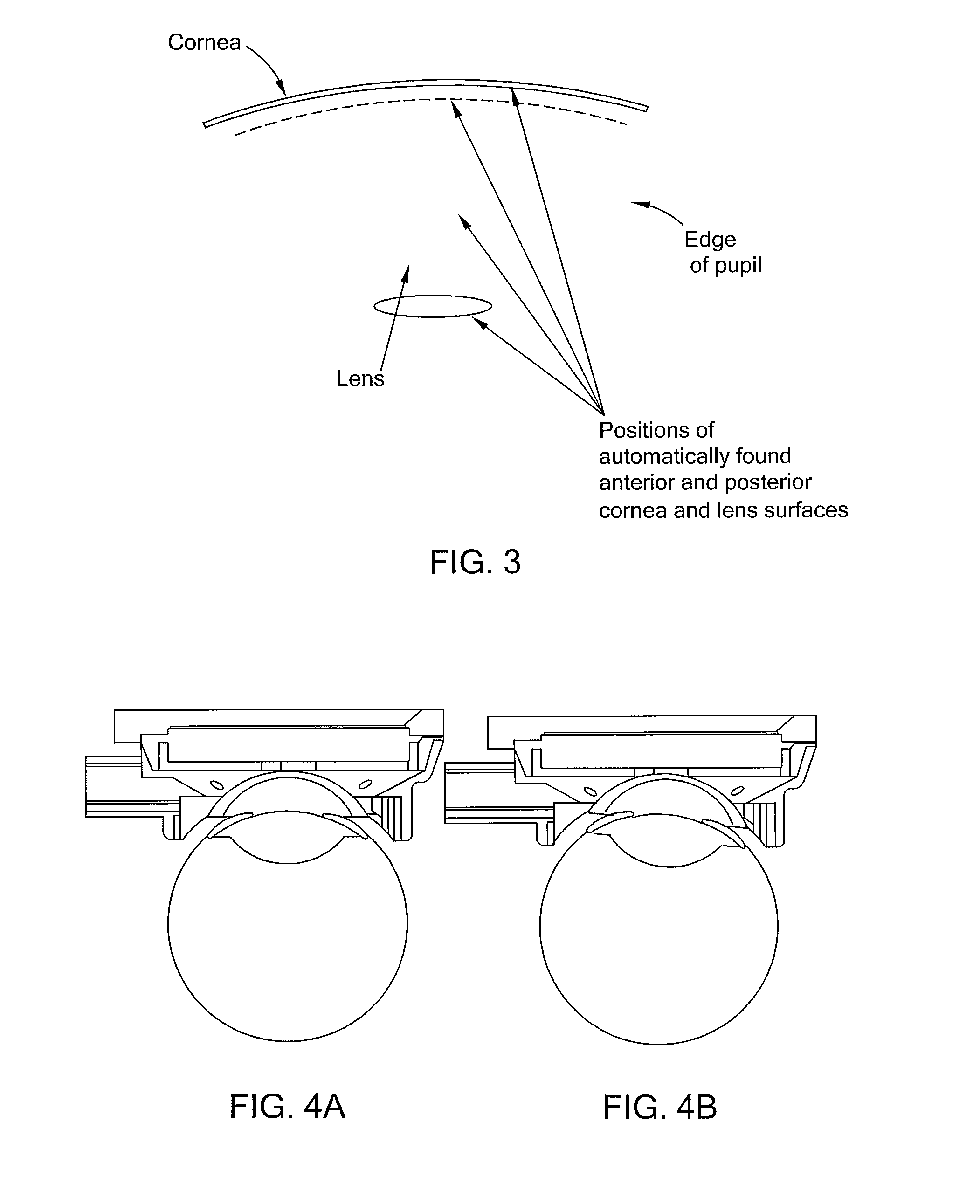
[0031]In accordance with the present invention, when two or more longitudinal sectional images of the eye are obtained, the positions of an optical surface (anterior or posterior cornea or lens surface), as characterized mathematically for each longitudinal sectional image, can be used to generate a three dimensional model of the surface, by curve fitting the edge points found from each image to the mathematical representation of a sphere, using a least squares algorithm. The process is repeated to obtain the mathematical representations of each of the anterior or posterior cornea or lens surfaces in terms of a best-fit sphere or other appropriate mathematical representation of the surfaces, such as modeling the surfaces in a Zernike polynomial expansion.

[0032]A particular process 200 for reconstructing a three dimensional model of the cornea and crystalline lens within a coordinate system defined by the camera and laser is shown in FIGS. 6 and 7. In the case of FIG. 6, only a singl...


PUM


Abstract

A method of generating three dimensional shapes for a cornea and lens, the method including illuminating an eye with multiple sections of light and obtaining multiple sectional images of the eye based on the multiple sections of light. For each obtained multiple sectional image, the following processes are performed:
    • a) automatically identifying arcs corresponding to anterior and posterior corneal and lens surfaces of the eye by image analysis and curve fitting of the obtained multiple sectional images; and
    • b) determining an intersection of lines ray traced back from the identified arcs with a known position of a section of space containing the section of light that generated the obtained multiple sectional images, wherein the intersection defines a three-dimensional arc curve. The method further including reconstructing three-dimensional shapes of the cornea surfaces and the lens surfaces based on fitting the three-dimensional arc curve to a three-dimensional shape.

Description

[0001]This application claims the benefit of priority under 35 U.S.C. §119(e)(1) of U.S. Provisional Application Ser. No. 61 / 467,601, filed Mar. 25, 2011, the entire contents of which is incorporated herein by reference.FIELD OF THE INVENTION[0002]The present invention relates to a method for generating three-dimensional images of a cornea and a lens of an eye and a method of surgically repairing an eye.BACKGROUND[0003]Obtaining the best laser phaco fragmentation results involves striking a balance between two opposing goals. The first opposing goal is to cut as much of the volume of the crystalline lens into suitable pieces as possible, particularly the cataract-hardened parts of the lens, so that as little ultrasound energy and mechanical manipulation of the lens as possible is required to remove the lens. Of necessity, this means making incisions as close as possible to the lens capsule, and particularly the posterior capsule where, for some types of cataracts, a hard, difficult-...

Claims


Application Information

Patent Timeline
IPC IPC(8): A61B18/20G06K9/78
CPCA61F9/008A61F2009/0087A61F2009/00889A61F2009/00878A61F2009/00872H04N19/523A61B3/10A61B3/145
Inventor GRAY, GARY P.FREY, RUDOLPH W.BOTT, STEVEN E.
Owner LENSAR LLC
Why Eureka
Try Eureka