
Image projection device and calibration method thereof

a projection device and image technology, applied in the field of image projection devices and calibration methods thereof, can solve the problems of long adjustment man-hours and high accuracy of parameter estimation, and achieve the effect of high accuracy

Active Publication Date: 2015-07-02
SONY CORP
View PDF7 Cites 36 Cited by
  • Summary
  • Abstract
  • Description
  • Claims
  • Application Information

AI Technical Summary

Benefits of technology

The patent text is about a new and improved image projection device that can capture and measure three dimensions accurately. It is designed to be easy to calibrate and adjust, and can provide high-quality images quickly. The technical effect is that this device can make it easier to measure and analyze objects in a more precise and efficient way.

Problems solved by technology

The estimation of parameters with high accuracy has a problem of long man-hours for adjustment.

Method used


Image

  • Image projection device and calibration method thereof
  • Image projection device and calibration method thereof
  • Image projection device and calibration method thereof

Examples


Embodiment Construction

)

[0049]Hereinafter, preferred embodiments of the present disclosure will be described in detail with reference to the appended drawings. Note that, in this specification and the appended drawings, structural elements that have substantially the same function and structure are denoted with the same reference numerals, and repeated explanation of these structural elements is omitted.

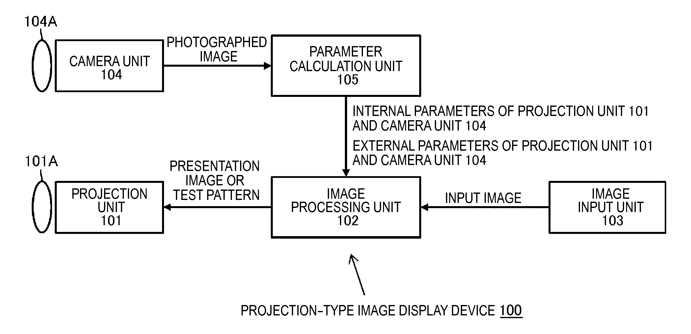
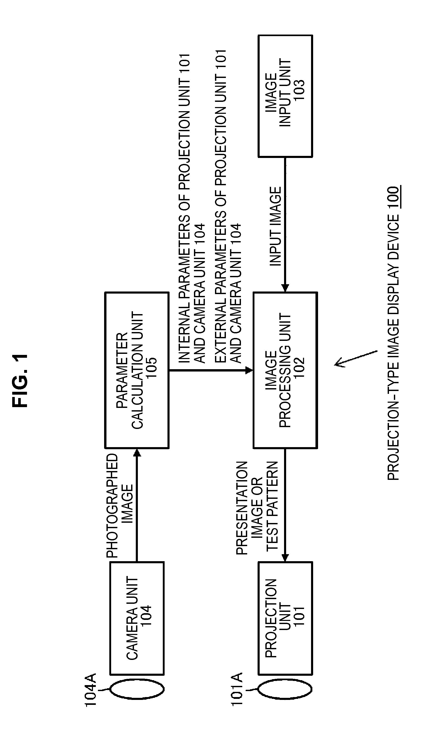
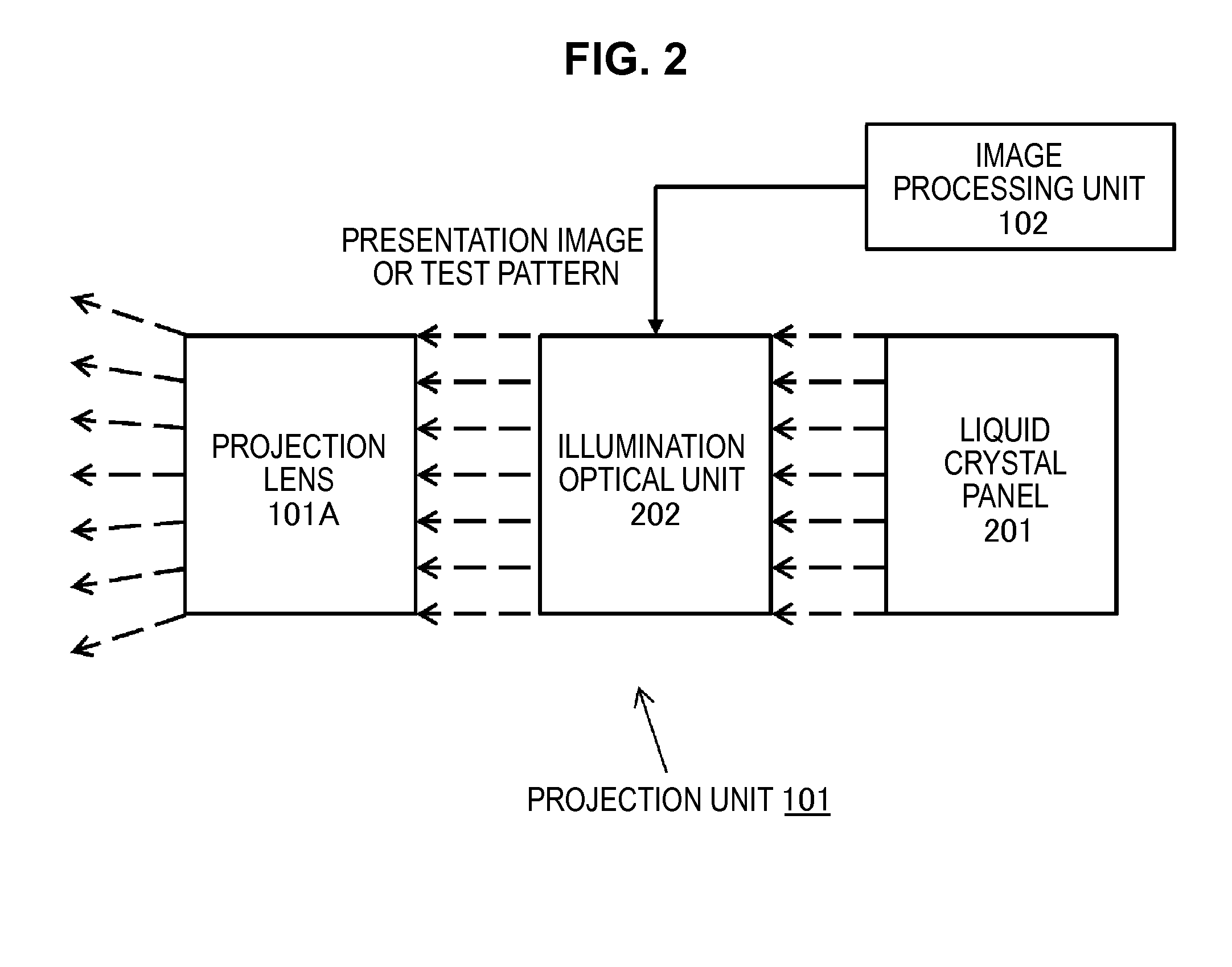
[0050]FIG. 1 schematically illustrates a configuration of the projection-type image display device 100 according to an embodiment of the technology disclosed in the present specification. One use of the projection-type image display device 100 is enlarged projection of a screen, and another use is three-dimensional measurement. The projection-type image display device 100 illustrated in FIG. 1 includes a projection unit 101, the image processing unit 102, an image input unit 103, the camera unit 104, and a parameter calculation detection unit 105. Hereinafter, each unit will be described. The image input u...


PUM


Abstract

There is provided an image projection device including a camera, a projector configured to project an image, a camera calibration unit configured to perform calibration of the camera, a projector calibration unit configured to perform calibration of the projector, and an image correction unit configured to correct the image projected from the projector based on a result of the calibration. The projector calibration unit performs ray tracing of a known checker pattern on which structural light is projected by the projector, and estimates parameters by acquiring correspondence relation between a lattice point of the checker pattern and projector coordinates.

Description

CROSS REFERENCE TO RELATED APPLICATIONS[0001]This application claims the benefit of Japanese Priority Patent Application JP 2013-273260 filed Dec. 27, 2013, the entire contents of which are incorporated herein by reference.BACKGROUND[0002]The technology disclosed in the present specification relates to an image projection device capable of performing three-dimensional measurement by photographing a projection image with a camera and a calibration method thereof. There is known a three-dimensional measurement device combining a projector and a camera. In such a kind of device, a projector projects a known pattern image on an object, and the object on which the pattern image is projected is photographed with a camera. Then, the photographed image is subjected to image processing, thereby three-dimensional information of the object can be obtained.[0003]In the device combining a projector and a camera, it is necessary to perform calibration of parameters regarding both the projector an...

Claims


Application Information

Patent Timeline
Patent Type & Authority Applications(United States)
IPC IPC(8): H04N17/00G06T7/00
CPCH04N17/002G06T7/0018H04N17/004H04N9/3194H04N9/3182H04N9/3185G06T2207/10024G06T7/80G06T3/18G06T5/80
Inventor KAJI, YOHSUKE
Owner SONY CORP
Learn More