Three-dimensional object detection device, and three-dimensional object detection method

a three-dimensional object and detection device technology, applied in the field of three-dimensional object detection devices and three-dimensional object detection methods, can solve problems such as the inability to appropriately detect three-dimensional objects

Active Publication Date: 2015-07-09
NISSAN MOTOR CO LTD +1
View PDF1 Cites 22 Cited by
  • Summary
  • Abstract
  • Description
  • Claims
  • Application Information

AI Technical Summary

Benefits of technology

[0009]According to the present invention, by extracting the edges from a first edge extraction area from which the extraction of a predetermined quantity of edges are expected during the daytime or by extracting the edges from a second edge extraction area from which the extraction of a predetermined quantity of edges are expected during the nighttime, and then calculating the intensity of the edges, appropriately determining whether or not the lens is clouded according to the surrounding light environment based on the intensity of the edges is possible. Then, by controlling the detection of a three-dimensional object based on the intensity of the edges, appropriately detecting a three-dimensional object even when the lens is clouded is possible.

Problems solved by technology

When detecting a three-dimensional object near a host vehicle based on a captured image captured by a camera and foreign matter, such as a water stain, is adhered to the camera lens, clouding the lens (a white thin film has formed on the lens surface), there are cases in which a part of the light flux from a subject will be blocked or irregularly reflected when the light environment differ between daytime and night, and the image of the subject that is captured by the camera becomes blurred; as a result, a three-dimensional object could not be appropriately detected.

Method used


Image

  • Three-dimensional object detection device, and three-dimensional object detection method
  • Three-dimensional object detection device, and three-dimensional object detection method
  • Three-dimensional object detection device, and three-dimensional object detection method

Examples


embodiment 1

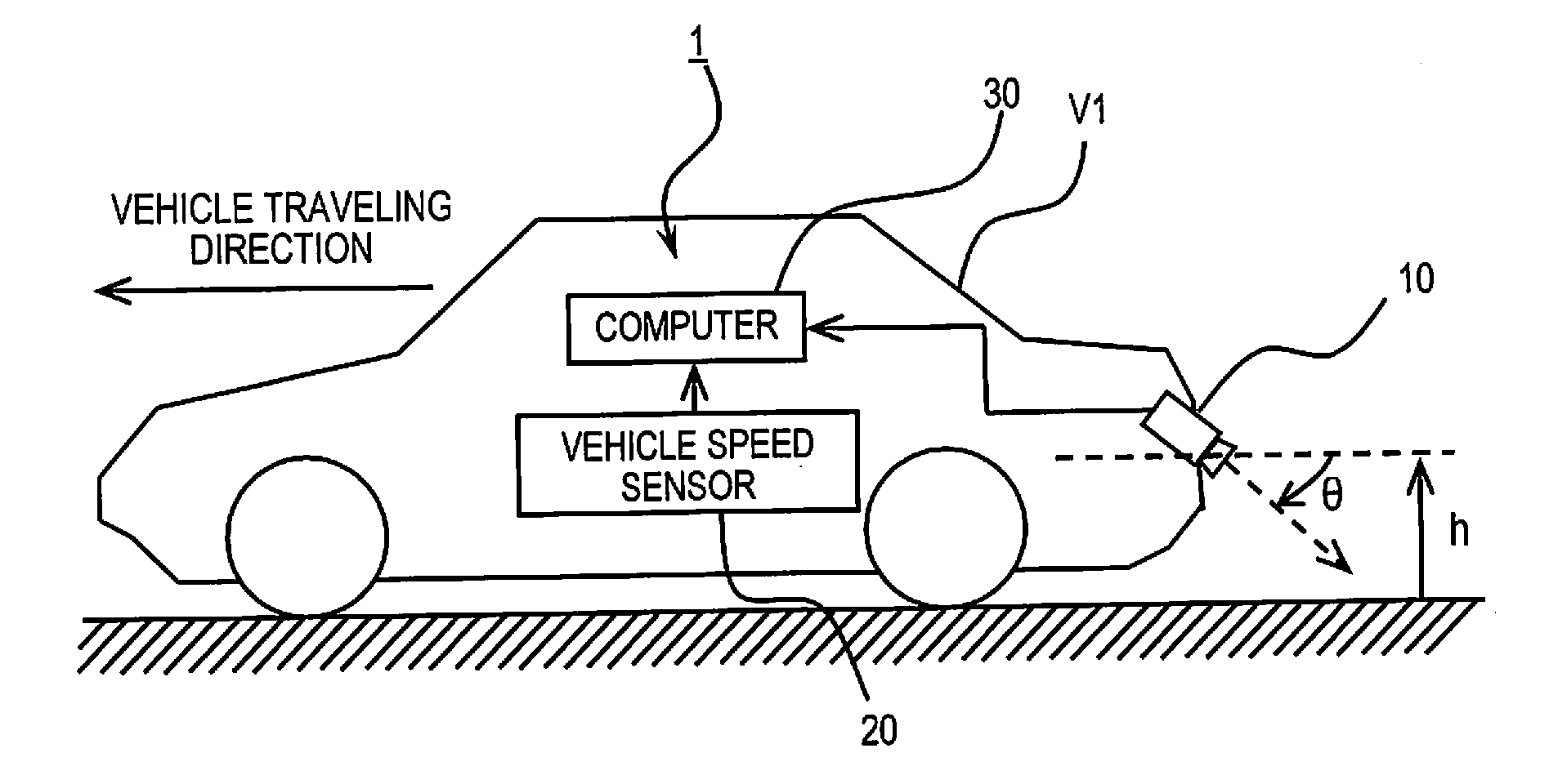
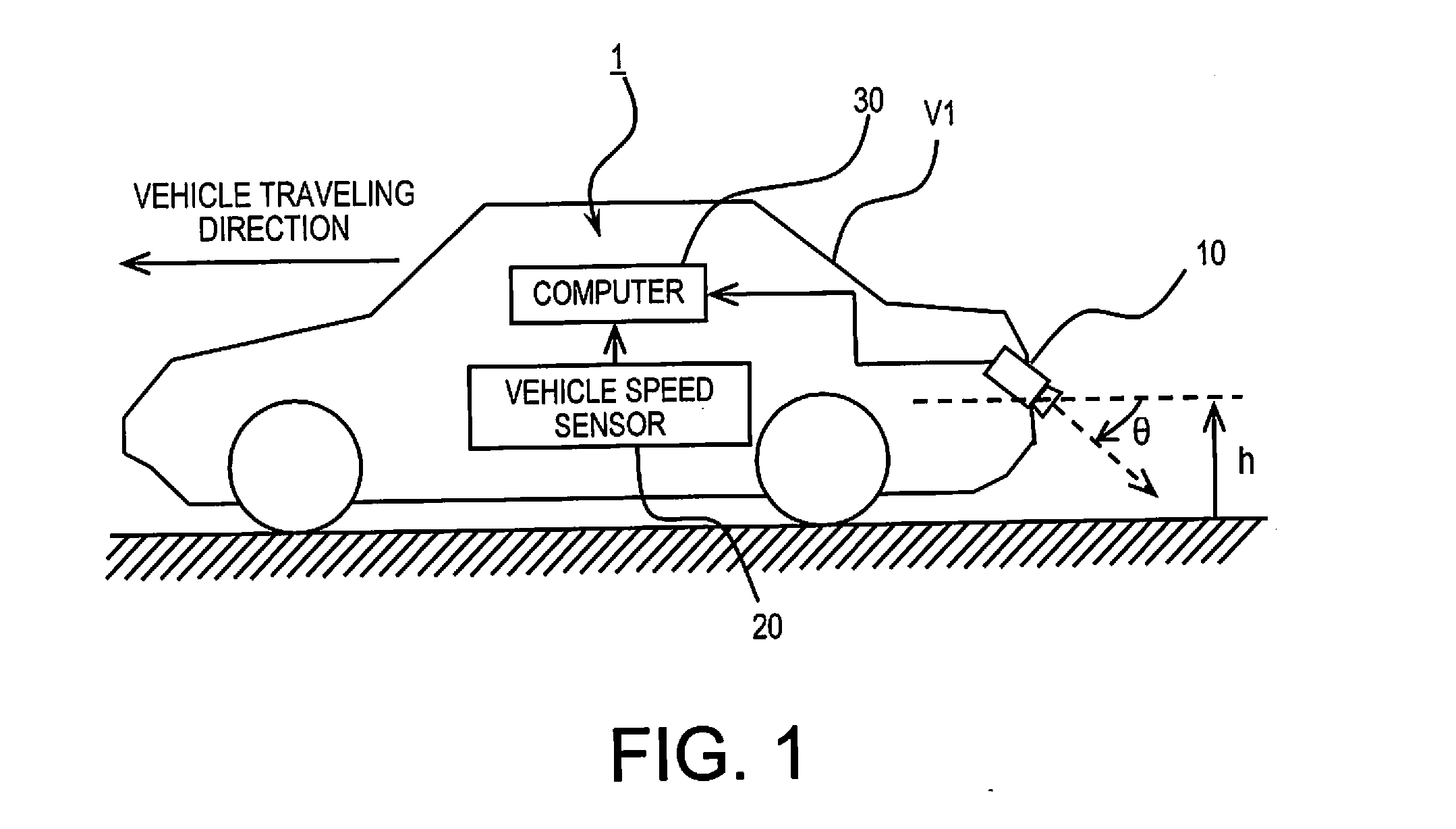
[0042]FIG. 1 is a schematic overview of a vehicle equipped with a three-dimensional object detection device 1 according to the present embodiment. An objective of the three-dimensional object detection device 1 according to the present embodiment is to detect another vehicle (which may hereinafter be referred to as adjacent vehicle V2) present in an adjacent lane where contact is possible should a host vehicle V1 change lanes. The three-dimensional object detection device 1 according to the present embodiment is provided with a camera 10, a vehicle speed sensor 20, and a computer 30, as illustrated in FIG. 1.

[0043]The camera 10 is attached to the host vehicle V1 so that the optical axis is an angle θ downward from the horizontal axis in a location at a height h at the rear of the host vehicle V1, as illustrated in FIG. 1. From this position, the camera 10 captures a predetermined area of the surrounding environment of the host vehicle V1. The vehicle speed sensor 20 detects the driv...

embodiment 2

[0132]Described next is a three-dimensional object detection device 1a according to the second embodiment. The three-dimensional object detection device 1a according to the second embodiment is the same as that of the first embodiment, except that a computer 30a is provided in lieu of the computer 30 of the first embodiment, as illustrated in FIG. 20; the operation is as described below. Here, FIG. 20 is a block view illustrating the details of the computer 30a according to the second embodiment.

[0133]The three-dimensional object detection device 1a according to the second embodiment is provided with a camera 10 and a computer 30a, as illustrated in FIG. 20. The computer 30a is provided with a viewpoint conversion unit 31, a luminance difference calculation unit 38, an edge line detection unit 39, a three-dimensional object detection unit 33a, a day / night assessment unit 34, an edge extraction area setting unit 35, an edge intensity calculation unit 36, and a threshold value changin...

embodiment 3

[0197]Described next is a three-dimensional object detection device 1b according to the third embodiment. The three-dimensional object detection device 1b according to the third embodiment is the same as that in the first embodiment, except that a computer 30b is provided in lieu of the computer 30 of the first embodiment, as illustrated in FIG. 28; the operation is as described below. Here, FIG. 28 is a block view illustrating the details of the computer 30b according to the third embodiment.

[0198]The computer 30b according to the third embodiment assesses whether or not the lens is clouded and conducts exposure control of the camera 10 according to the turbidity of the lens in order to appropriately detect a three-dimensional object even when the lens of the camera 10 is clouded (when white thin film caused by a water stain or the like has formed on the lens surface). In order to realize this type of function, the computer 30b is provided with an exposure controller 40 in lieu of ...


PUM


Abstract

A three-dimensional object detection device has an image capturing unit, an object detection unit, first and second edge intensity calculation units, a day/night assessment unit and a controller. The day/night assessment unit assess whether it is currently daytime or nighttime when detecting a three-dimensional object based on the captured images. Upon assesses it is daytime, edges of a subject are extracted from a first edge extraction area, including a horizon reference area, and a threshold value for detecting the three-dimensional object is set based on the intensity of the edges in the first edge extraction area. Upon assesses it is nighttime, the edges of a subject are extracted from a second edge extraction area, including a road edge reference area, and a threshold value for detecting the three-dimensional object is set based on the intensity of the edges that are extracted from the second edge extraction area.

Description

CROSS-REFERENCE TO RELATED APPLICATIONS[0001]This application is a U.S. National stage application of International Application No. PCT / JP2013 / 070309, filed Jul. 26, 2013, which claims priority to Japanese Patent Application No. 2012-166528 filed in Japan on Jul. 27, 2012 and Japanese Patent Application No. 2012-166529 filed in Japan on Jul. 27, 2012.BACKGROUND[0002]1. Field of the Invention[0003]The present invention relates to a three-dimensional object detection device and a three-dimensional object detection method.[0004]2. Background Information[0005]In a conventionally known technique, a three-dimensional object near a host vehicle is detected based on a captured image captured by a camera (see Japanese Laid-Open Patent Application No. 2006-311216).SUMMARY[0006]When detecting a three-dimensional object near a host vehicle based on a captured image captured by a camera and foreign matter, such as a water stain, is adhered to the camera lens, clouding the lens (a white thin film...

Claims


Application Information

Patent Timeline
Patent Type & Authority Applications(United States)
IPC IPC(8): H04N7/18G06K9/00B60R1/00G06T7/00G06V10/141G06V10/44
CPCH04N7/188G06T7/0042G06K9/00201B60R1/00G06T7/0085G06T2207/30261H04N2101/00B60R2300/8026G06T2207/10028B60R2300/607G06T2207/20148G06K9/00805G03B2217/005G06T7/12G06T7/136G06V20/64G06V20/58G06V10/141G06V10/44H04N23/81H04N23/61
Inventor HAYAKAWA, YASUHISAFUKATA, OSAMUTAKEMURA, MASAYUKIUTAGAWA, AKIRAMURAMATSU, SHOJIIRIE, KOTA
Owner NISSAN MOTOR CO LTD
Why Eureka
Try Eureka