LED lighting system

a technology of led lighting and led lamps, which is applied in the direction of lighting and heating equipment, instruments, process and machine control, etc., can solve the problems of higher voltage drop across the entire led string of lamps, and achieve the effect of reducing the number of components and ensuring the efficiency of the energy storage circui

Active Publication Date: 2015-07-16
SILICON HILL
View PDF9 Cites 38 Cited by
  • Summary
  • Abstract
  • Description
  • Claims
  • Application Information

AI Technical Summary

Benefits of technology

[0021]Alternatively, the first and second circuit configurations may differ in the number of the groups of LEDs connected in series versus the number of groups connected in parallel. The first circuit configuration may comprise a greater number of the LEDs connected in a series string than the second circuit configuration. In one embodiment, the first circuit configuration corresponds to a series connection of all of the groups of LEDs, i.e. all of the groups are connected together in a series circuit. The second circuit may be adapted to connect the plurality of groups of LEDs into the first circuit configuration when the output from the first circuit indicates the ballast is a magnetic ballast. Thus, when the LED lamp arrangement is supplied with power by a magnetic ballast, the groups of LEDs may be connected together in a series circuit, leading to a higher voltage drop across the complete LED string of the lamp.
[0063]The sixth circuit for sensing a frequency may be constructed similarly to the first circuit of the first aspect of the invention, and the first circuit for sensing a frequency and the sixth circuit for sensing a frequency may be embodied at least in part in the same circuit element or elements. In this way, the first and sixth circuit can use some or all of the same circuit elements to reduce the number of components required.

Problems solved by technology

Thus, when the LED lamp arrangement is supplied with power by a magnetic ballast, the groups of LEDs may be connected together in a series circuit, leading to a higher voltage drop across the complete LED string of the lamp.

Method used


Image

  • LED lighting system
  • LED lighting system
  • LED lighting system

Examples


Embodiment Construction

[0084]An explanation with respect to features of embodiments of the invention with respect to technical properties and phenomena is provided, followed by exemplary embodiments of the present invention.

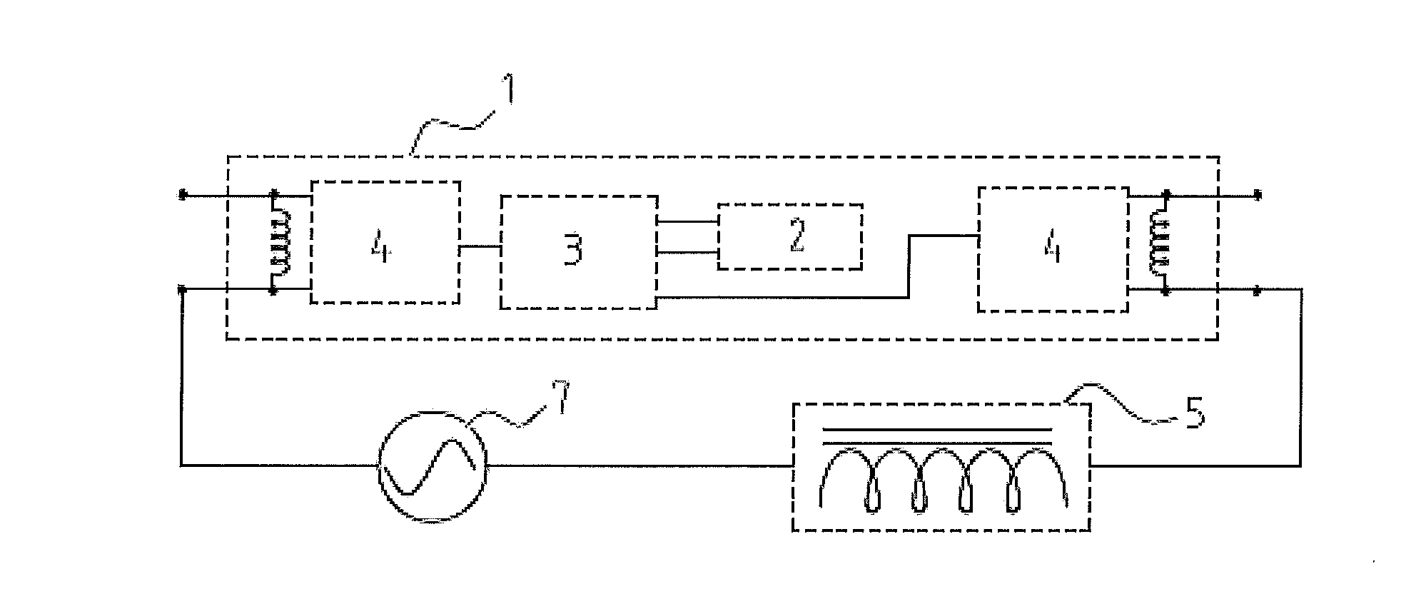
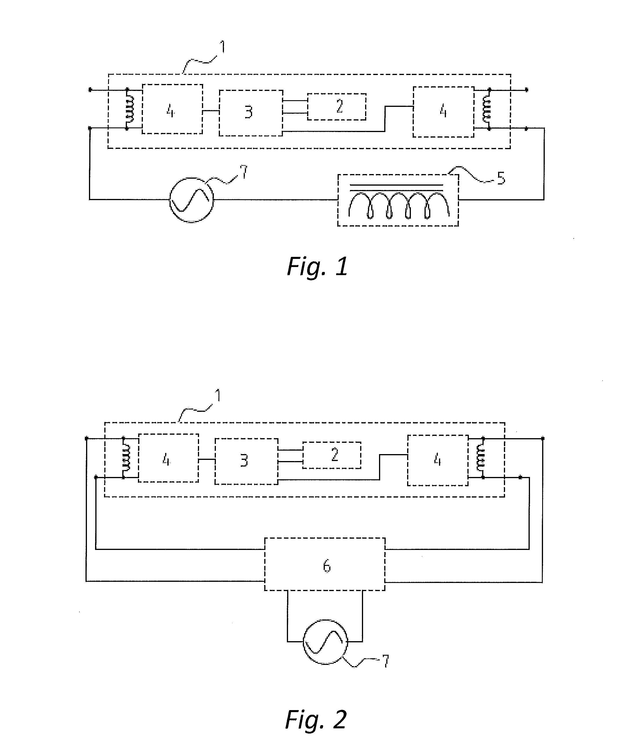
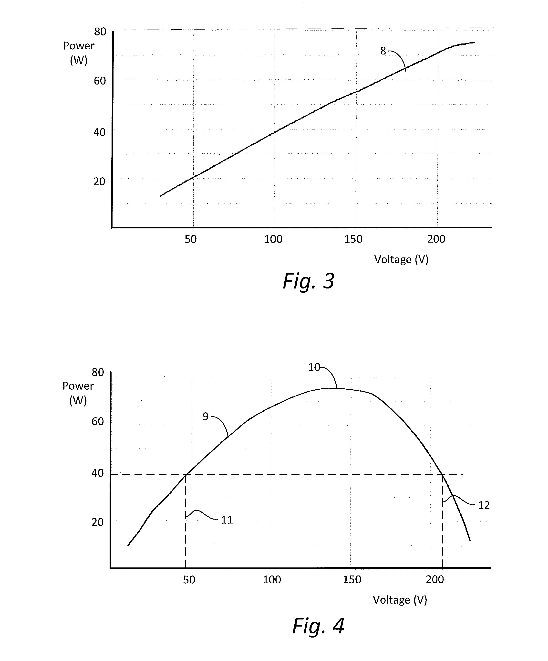
[0085]Both magnetic and electronic ballasts are designed to start, control and to limit current supplied to a fluorescent tube and regulate the power consumed by the tube. Because of the electronic characteristics of LEDs, embodiments of the present invention are based on the surprising insight that both types of ballasts can be adapted to function as crude LED drivers, in which the total forward voltage of one or more strings or groups with a specific number of LEDs determines the actual consumed power.

[0086]An LED (light emitting diode) is a semiconductor light source, e.g. with a pn-junction which emits light when activated. When a suitable voltage is applied, electrons are able to recombine with electron holes within the device, releasing energy in the form of photons. This effect ...


PUM


Abstract

An LED lamp arrangement adapted to replace a fluorescent lamp in a luminaire having a ballast for supplying power to the lamp. The LED lamp arrangement comprises a plurality of LEDs arranged in a plurality of groups, wherein the groups of LEDs are connectable in a plurality of circuit configurations, including at least a first circuit configuration, and a second circuit configuration having a different circuit arrangement of the groups of LEDs in which at least a portion of the groups of LEDs are connected into the circuit differently than in the first circuit configuration. The LED lamp arrangement further comprises a first circuit adapted to generate an output indicating whether the ballast is a magnetic ballast or a non-magnetic ballast, and a second circuit adapted to change a connection of the plurality of groups of LEDs between the first circuit configuration and the second circuit configuration on the basis of the output of the first circuit.

Description

CROSS REFERENCE TO RELATED APPLICATIONS[0001]This application is a continuation-in-part of PCT application number PCT / EP2014 / 070568 filed on Sep. 25, 2014, which claims priority from Netherlands application number 2011495 filed on Sep. 25, 2013. Both applications are hereby incorporated by reference in their entireties.BACKGROUND OF THE INVENTION[0002]1. Field of the Invention[0003]The invention relates generally to LED lamps and LED lighting, and more particularly to LED lamps suitable to replace a fluorescent lamp in a luminaire having a ballast for use with fluorescent lamps.[0004]2. Description of the Related Art[0005]Fluorescent lighting has been around for many years now. This form of lighting started out as a highly efficient alternative for incandescent light bulbs, but has recently been surpassed by LED lighting to some extent in terms of efficiency and power consumption, and also in other aspects as set out below.[0006]Fluorescent lamps generally comprise a tube filled wit...

Claims


Application Information

Patent Timeline
Patent Type & Authority Applications(United States)
IPC IPC(8): F21K99/00H05B33/08H05B44/00
CPCF21K9/175H05B33/0851H05B33/083H05B33/0827F21K9/27H05B45/44H05B45/3578H05B45/59H05B45/46H05B45/48Y02B20/30
Inventor SEGERS, MAARTEN WILLEMROY, SHOUNAKSTEFFENS, PAULGROENENDAAL, TOONHONOLD, JURGEN
Owner SILICON HILL
Why Eureka
Try Eureka