
Inner image generating apparatus and method thereof

a technology of inner image and generating apparatus, which is applied in the direction of optical radiation measurement, radiation particle tracking, instruments, etc., can solve the problems of low resolution of imaged objects, resolution to deteriorate, and resolution to deteriorate, and achieve high resolution

Active Publication Date: 2015-07-16
KK TOSHIBA
View PDF4 Cites 2 Cited by
  • Summary
  • Abstract
  • Description
  • Claims
  • Application Information

AI Technical Summary

Benefits of technology

The objective of this patent is to provide methods for creating high-resolution images of structures.

Problems solved by technology

For this reason, influences of Coulomb multiple scattering when the muon penetrates the structure are not taken into consideration and this method has a problem that resolution of an imaged object is low.
However, since the scattering angle of Coulomb multiple scattering depends on energy of inlet particles, there is a problem that the resolution of the object estimated from the scattering angle deteriorates due to influences of a fluctuation portion of energy.
Thus, the existing methods include factors that cause the resolution to deteriorate, and it is therefore difficult to generate an image of a large-scale structure such as an atomic power plant with high resolution.

Method used


Image

  • Inner image generating apparatus and method thereof
  • Inner image generating apparatus and method thereof
  • Inner image generating apparatus and method thereof

Examples


Embodiment Construction

[0019]Hereinafter, an embodiment will be described with reference to the accompanying drawings.

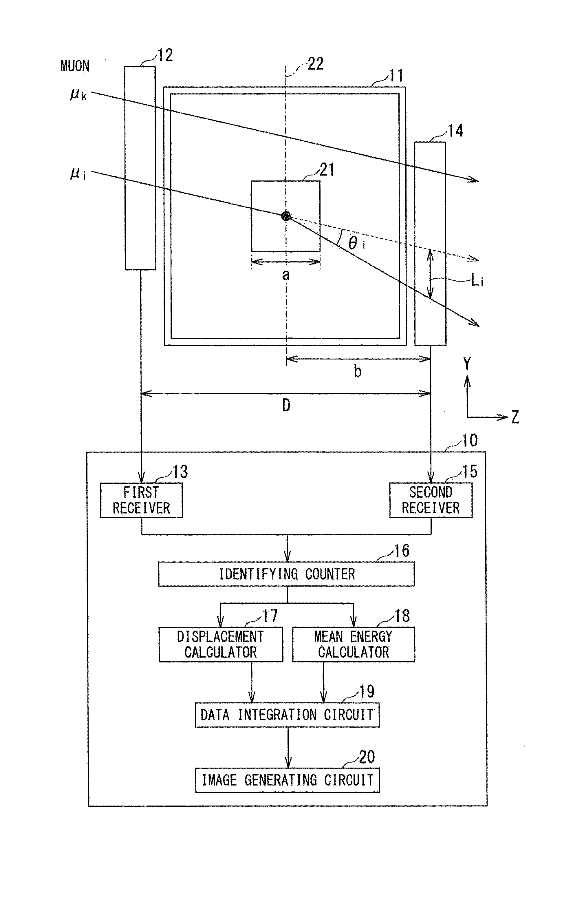
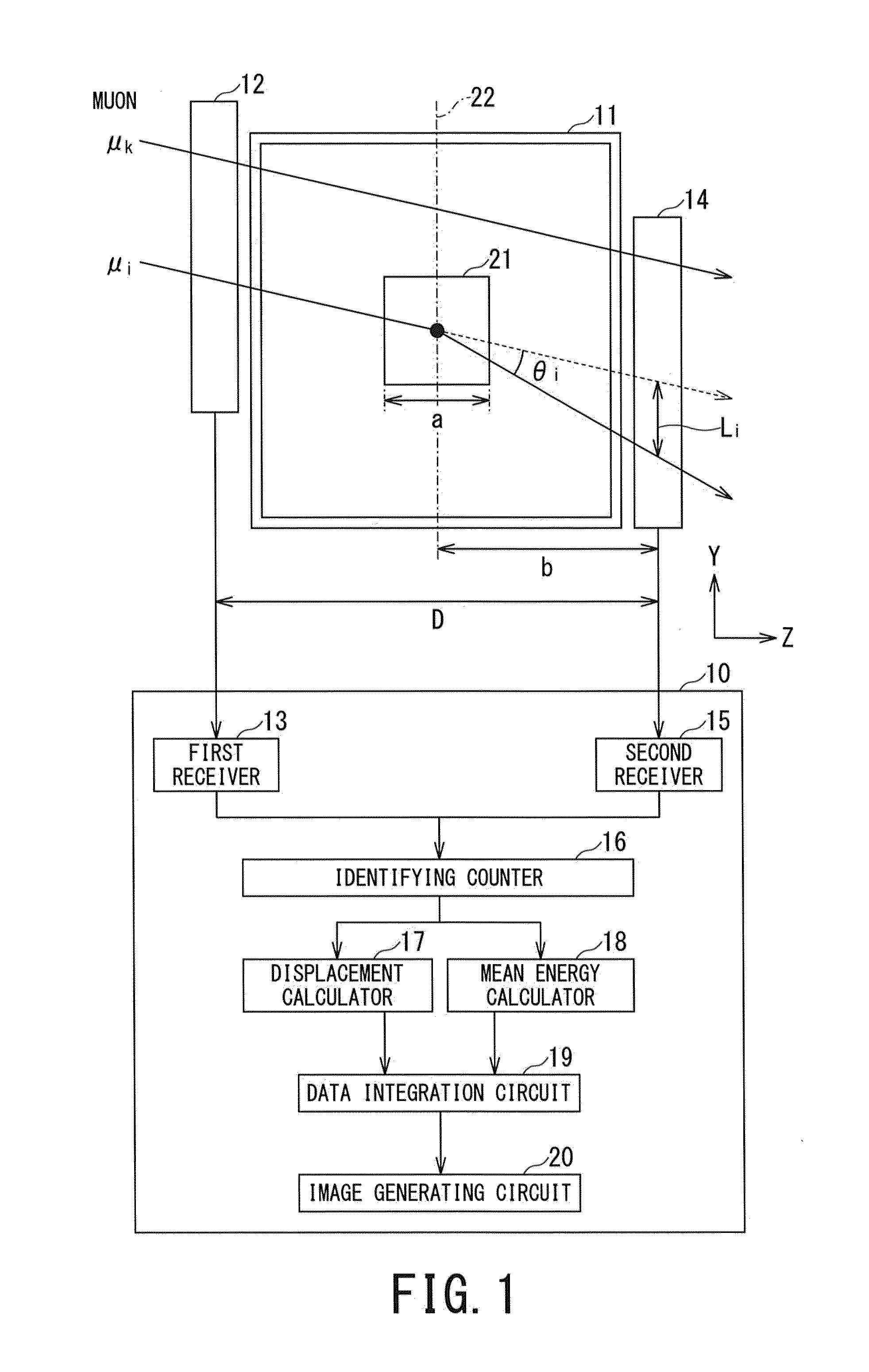
[0020]An inner image generating apparatus 10 (hereinafter referred to as “image generating apparatus 10”) according to the present embodiment shown in FIG. 1 is provided with a first receiver 13 that receives inlet track information and a passage time of a muon incident on a structure 11 at a first track detector 12 provided outside of the structure 11, a second receiver 15 that receives outlet track information and a passage time of the muon having passed the structure 11 from a second track detector 14 provided outside of the structure 11 at an opposite side of the first track detector 12, a displacement calculator (track displacement calculator) 17 that calculates an estimated track estimated from the inlet track and calculates a track displacement of the muon based on the estimated track and the outlet track, a mean energy calculator 18 that calculates mean energy of the muon based on ...


PUM

PropertyMeasurementUnit
mean energyaaaaaaaaaa
zenith anglesaaaaaaaaaa
diameteraaaaaaaaaa

Abstract

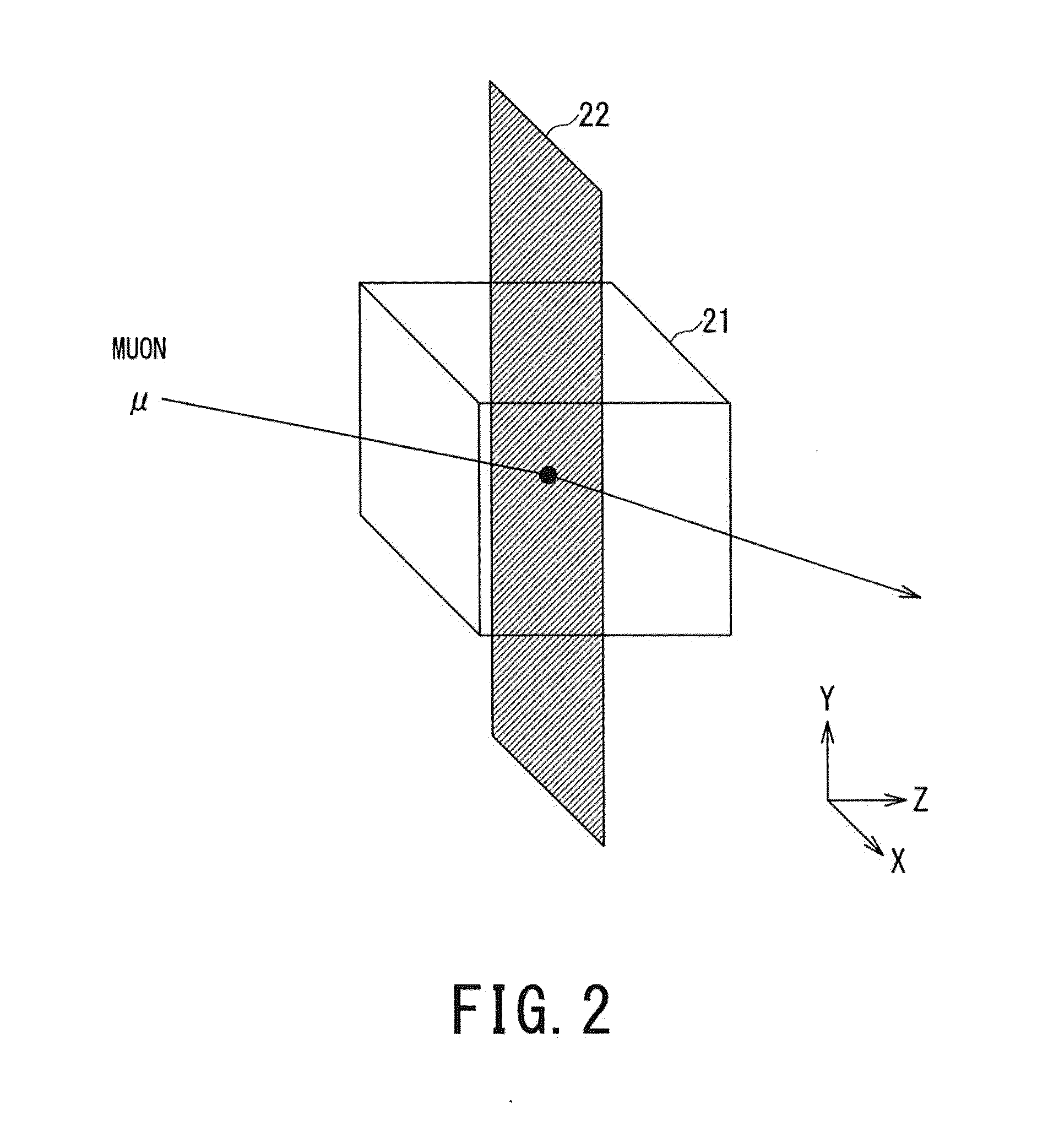
An inner image generating apparatus includes a first receiver configured to receive an inlet track information and a first passage time of a muon, a second receiver configured to receive an outlet track information and a second passage time of the muon, a displacement calculator configured to calculate a track displacement of a track of the muon based on the inlet and outlet track information, a mean energy calculator configured to calculate a mean energy of the muon based on a time-difference between the first passage and the second passage time, a data integration circuit configured to integrate multiplied data multiplying the track displacement and the mean energy on a projected plane, and an image generating circuit configured to generate an inner image of the structure by identifying a position of matter at the projected plane based on an integrated multiplied data.

Description

CROSS-REFERENCE TO RELATED APPLICATION [0001]This application is based upon and claims the benefit of priority from Japanese Patent application No. 2014-004524, filed on Jan. 14, 2014, the entire content of which is incorporated herein by reference.FIELD OF THE INVENTION [0002]Embodiments of the present invention relate to an inner image generating technique that generates an image of an inside of a structure using cosmic radiation muons.RELATED ART[0003]As a conventional technique of grasping an inside of a structure, a technique is known which observes muons that arrive at the surface of the earth and sees through the inside of the structure.[0004]The muon is a kind of secondary cosmic radiation generated when primary cosmic radiation entering the earth from outer space reacts with the atmosphere of the earth. The muon has positive or negative charge, has high mean energy of 3 to 4 GeV and therefore possesses high penetrability.[0005]The technique of seeing through a structure usi...

Claims


Application Information

Patent Timeline
Patent Type & Authority Applications(United States)
IPC IPC(8): G01N23/04G01T5/02G01T5/00
CPCG01N23/04G01T5/02G01T5/002G01V5/22
Inventor SUGITA, TSUKASAMIYADERA, HARUOYOSHIOKA, KENICHIKUME, NAOTONAKAYAMA, KOHICHIBAN, YUICHIROKARINO, YOSHIJIFUJITA, KYOUICHIODANAKA, SHIGERU
Owner KK TOSHIBA
Learn More