
Battery module and heat dissipating unit thereof

Inactive Publication Date: 2015-07-16
SIMPLO TECH COMPANY
View PDF0 Cites 68 Cited by
  • Summary
  • Abstract
  • Description
  • Claims
  • Application Information

AI Technical Summary

Benefits of technology

The present patent solves the problem of poor contact between a coolant heat dissipating unit and batteries due to thermal expansion of the batteries, which causes poor rate of heat dissipation. The heat dissipating unit has an expandable fluid channel that can transmit heat produced by the battery cell outward effectively by pushing the side wall of the channel using a coolant. The flexible side wall of the channel maintains a tight contact with the battery cells when the casing expands outward due to heat. The expandable fluid channel also has the ability to restrict and fix the position of the battery cells, increasing the resistance to shock of the battery module when the vehicle travels. The use of metal material as the heat dissipating unit achieves high rate of heat dissipation and stabilizes the output voltage of the battery module.

Problems solved by technology

Safety and stability of operation are important issues for batteries.
When heat inside the battery module cannot be dissipated, long periods of charge or discharge necessarily produce high temperatures in the battery module.
When the temperature rises, the casing of the battery module often deforms due to heat, and the high temperature affects the capacity of the battery, reducing the efficacy of the batter or even affecting the functionality of the circuit board and the circuit components thereof, in turn increasing risks of burning or explosion.
Therefore, especially in the field of electric vehicles, heat dissipation for battery modules is an especially important issue.
The disadvantages of heat dissipation via convection by air are lower rate of dissipation, greater variance in temperature between batteries, and an open design which is vulnerable to foreign particles such as dust.
The disadvantage of heat dissipation via convection by fluid is that heat dissipation channels need to be designed for cooling fluids, and the heat dissipation channels need to be in close contact with the batteries in order to achieve the effect of heat dissipation.
When using rectangularly shaped or soft pack batteries, the casing of the battering expands due to high temperature.
The disadvantage of this method is that typical metal are not easily compressible material, and more compressible material are non-metal having lower heat conduction rates than those of metal.

Method used


Image

  • Battery module and heat dissipating unit thereof
  • Battery module and heat dissipating unit thereof
  • Battery module and heat dissipating unit thereof

Examples


first embodiment

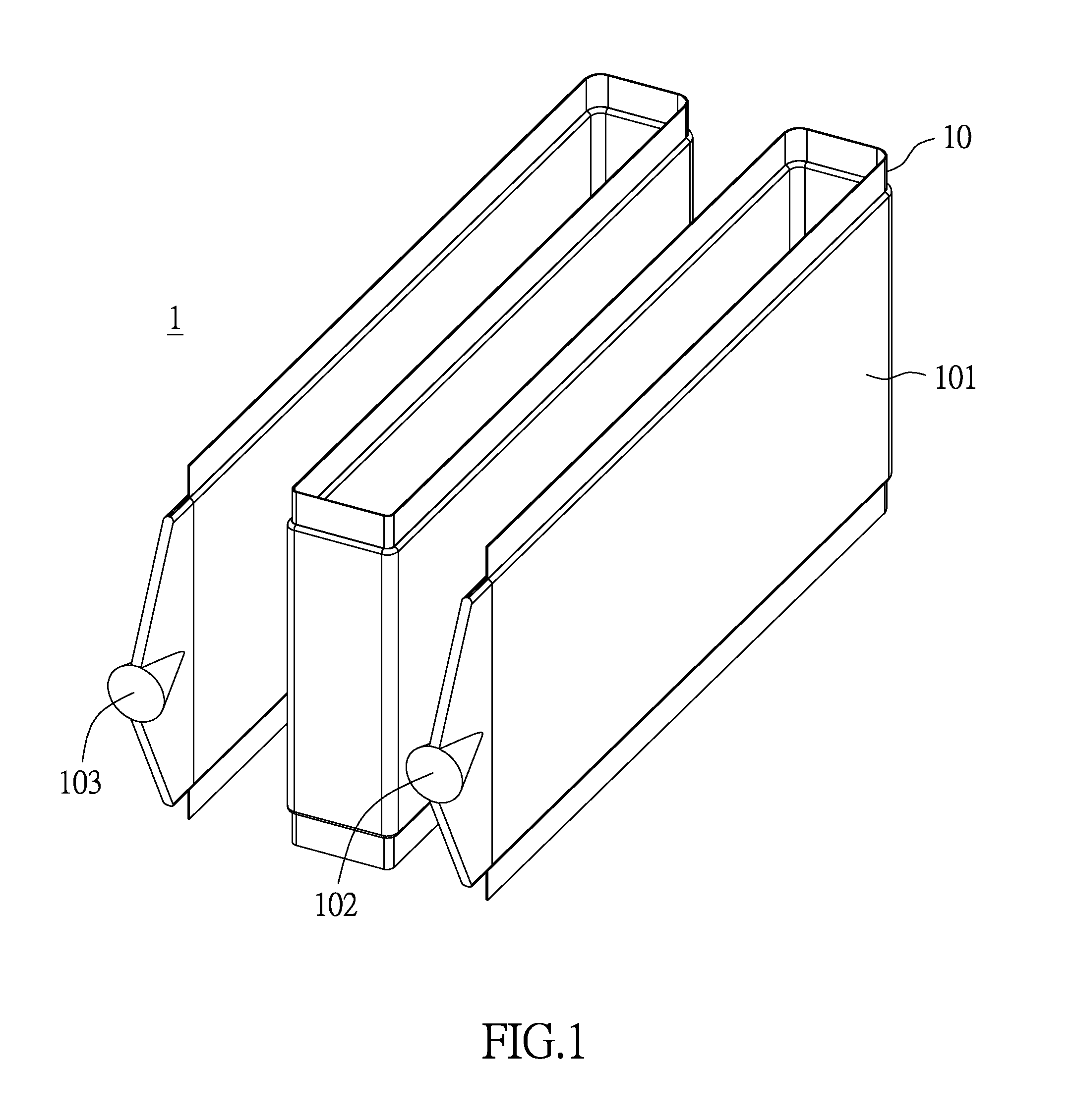
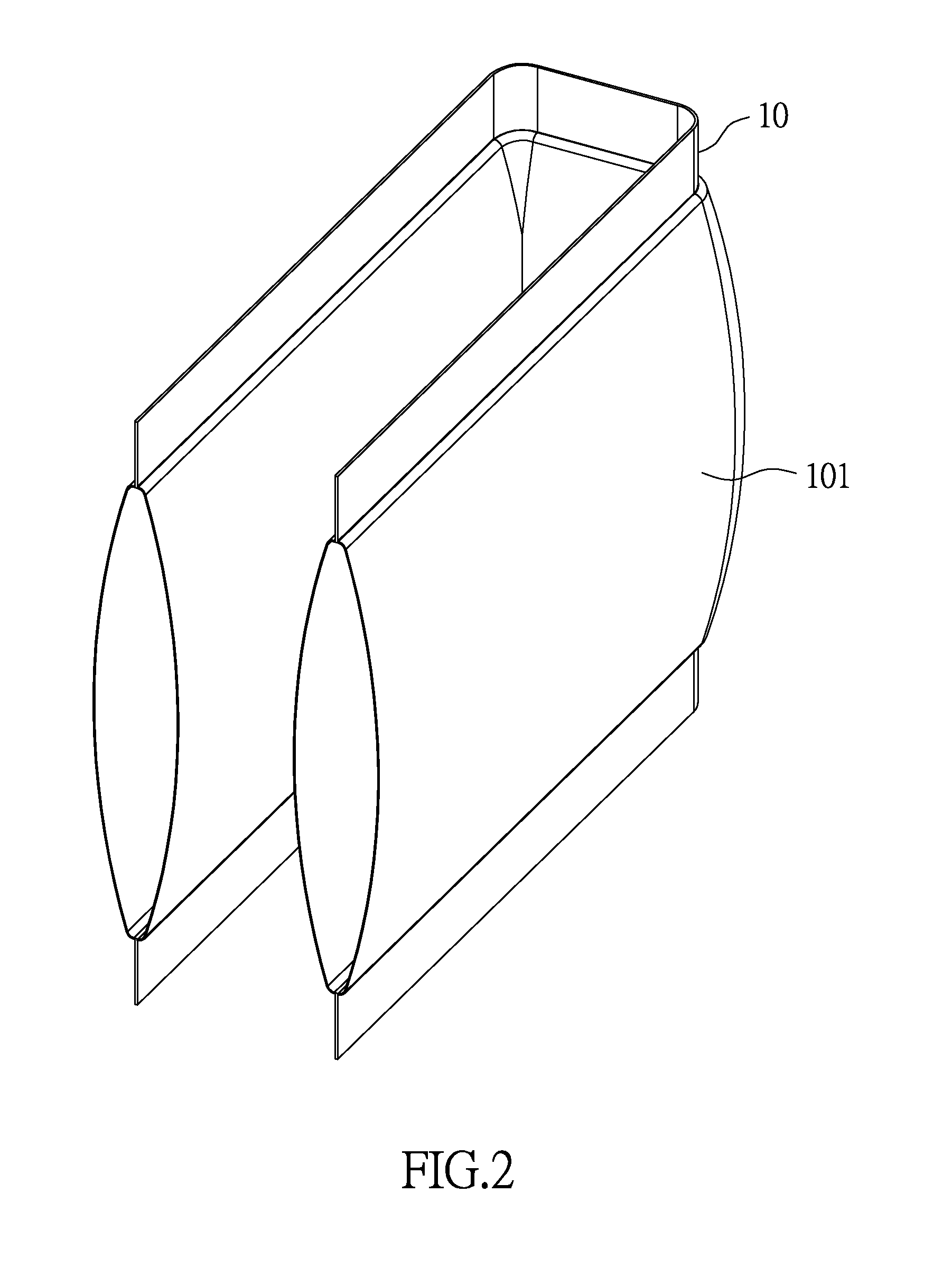
[0032]FIG. 1 and FIG. 2 show a heat dissipating unit according to the present disclosure. As shown in the figures, the heat dissipating unit 1 includes a main body 10, which includes an expandable fluid channel 101, a fluid inlet 102 and a fluid outlet 103. The expandable fluid channel 101, the fluid inlet 102 and the fluid outlet 103 are communicated. The main body 10 can be made of a flexible material, and can be bent or wound according to the space created by the arrangement and physical shape of the battery cells. Therefore, the heat dissipating unit 1 can be applied in wide range of types of battery modules, e.g. cylindrically shaped, rectangularly shaped or soft pack batteries. In one embodiment, the main body 10 can be made of an inflexible material, and the shape of the main body 10 is chosen according to the space created by the arrangement and physical shape of the battery cells.

[0033]Specifically, in the figures of the present embodiment, the heat dissipating unit 1 is ri...

second embodiment

[0038]FIG. 5 and FIG. 6 show the aforementioned heat dissipating unit applied to a battery module. As shown in the figures, the battery module 2 includes a top cover 20, a heat dissipating unit 1, a set of battery cells 21 and a base plate 22. The heat dissipating unit 1 includes a main body 10, which includes an expandable fluid channel 101, a fluid inlet 102 and a fluid outlet 103. The expandable fluid channel 101, the fluid inlet 102 and the fluid outlet 103 are communicated. The present embodiment is not limited to what is shown in the figures of the present embodiment, and can implement features of the heat dissipating unit 1 of the previous embodiment, e.g. disposing the fluid inlet 102 and the fluid outlet 103 at any of the two ends of the main body 10, independently disposing a plurality of expandable fluid channels 101 at the heat dissipating unit 1, etc. (in the present embodiment, the fluid inlet 102 and the fluid outlet 103 are respectively disposed at two ends of the ma...

third embodiment

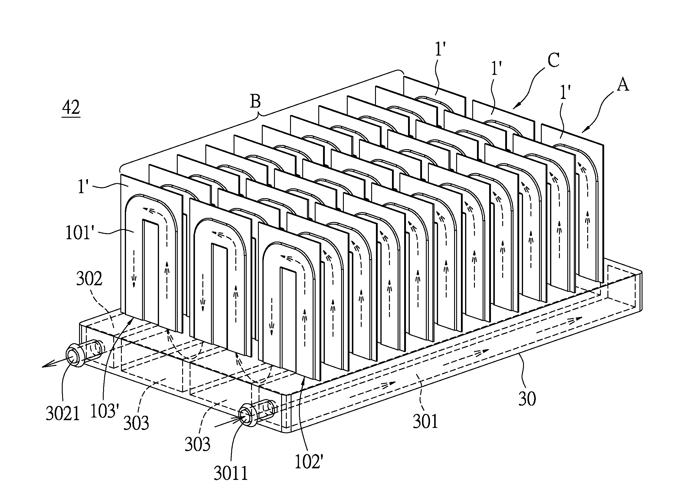
[0043]FIG. 7 to FIG. 9 show unitized modular heat dissipating units.

[0044]Different from the ribbon-shaped heat dissipating units 1 of the previous embodiments, the heat dissipating unit 1′ of the present embodiment is unitized and modular. As shown in FIG. 7, the main body 10′ of the heat dissipating unit 1′ can be a sheet-shaped unit structure, the expandable fluid channel 101′ can have a U-turn, and the two ends of the expandable fluid channel 101′ are respectively formed with a fluid inlet 102′ and a fluid outlet 103′. In practice, the appearance of the expandable fluid channel 101′ and the width of the same (before and after expansion) can be configured according to practical need (e.g. flow rate of the fluid) and designed accordingly without being limited to what is shown in the figures. Preferably, the expandable fluid channel 101′ is made of metal, e.g. aluminum.

[0045]Different from the previous embodiments, the heat dissipating units 1′ can be integrally formed by using fle...


PUM


Abstract

A battery module comprises a base, a set of battery cells and a plurality of heat dissipating units. The base comprises an input opening, an output opening and a plurality of fluid channels. A set of battery cells is disposed on the base and comprises a plurality of battery cells. A channel is formed between neighboring battery cells and the heat dissipating units are respectively disposed in the channels. Each heat dissipating unit has a main body having an expandable fluid channel, a fluid inlet and a fluid outlet. Each expandable fluid channel is communicated with the respective fluid inlet and the respective fluid outlet, and the expandable fluid channels are communicated with the fluid channels of the base. When a coolant flows into the expandable fluid channel, at least one side wall expands with the pressure of the coolant and contacts the surface of the battery cell.

Description

BACKGROUND OF THE INVENTION[0001]1. Field of the Invention[0002]The present disclosure relates to a battery module and a heat dissipating unit thereof; in particular, to a battery module including a flexible heat dissipating unit.[0003]2. Description of Related Art[0004]In recent years, driven by several factors, usage of batteries have become more and more widespread, and requirements for the batteries have become higher and higher. Safety and stability of operation are important issues for batteries. Of these issues, maintaining a stable temperature for the batteries is very important.[0005]Batteries used in electric vehicles or energy storage systems are typically cylindrically shaped, rectangularly shaped, or soft pack batteries. As known, when batteries are charged or discharged, heat is produced. Controlling the circuit and the components thereof of the battery module also produces heat. When heat inside the battery module cannot be dissipated, long periods of charge or discha...

Claims


Application Information

Patent Timeline
IPC IPC(8): H01M10/613F28F3/12
CPCF28F3/12H01M10/613F28F2275/10F28D1/035F28D1/0478F28D2021/0029F28F2265/26F28F2255/02H01M10/6557Y02E60/10
Inventor LEE, CHAO-FENGWU, WENCHIEN, CHIA-HUNG
Owner SIMPLO TECH COMPANY
Learn More