Apparatus and Methods for the Guidance of Fish

Inactive Publication Date: 2015-07-23
SMITH ROOT
View PDF24 Cites 12 Cited by
  • Summary
  • Abstract
  • Description
  • Claims
  • Application Information

AI Technical Summary

Benefits of technology

[0026]The apparatus and methods for the guidance of fish also includes an array barrier for the guidance of fish in a body of water that adjusts parts of the array to increase or reduce the electric field as needed

Problems solved by technology

Still larger potentials may result in unconciousness or complete euthanasia of the fish.
Some of the common problems with existing electrode arrays (with the possible

Method used


Image

  • Apparatus and Methods for the Guidance of Fish
  • Apparatus and Methods for the Guidance of Fish
  • Apparatus and Methods for the Guidance of Fish

Examples


Embodiment Construction

[0038]Representative embodiments according to the inventive subject matter are shown in FIGS. 1-3, wherein similar features share common reference numerals.

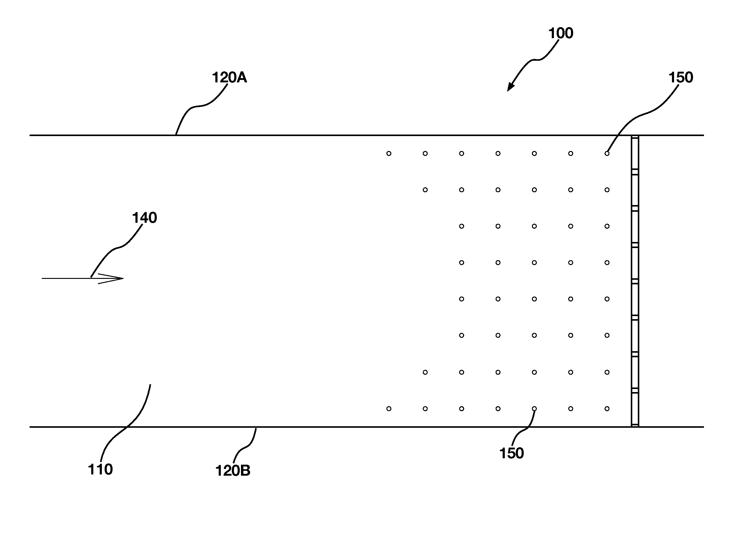
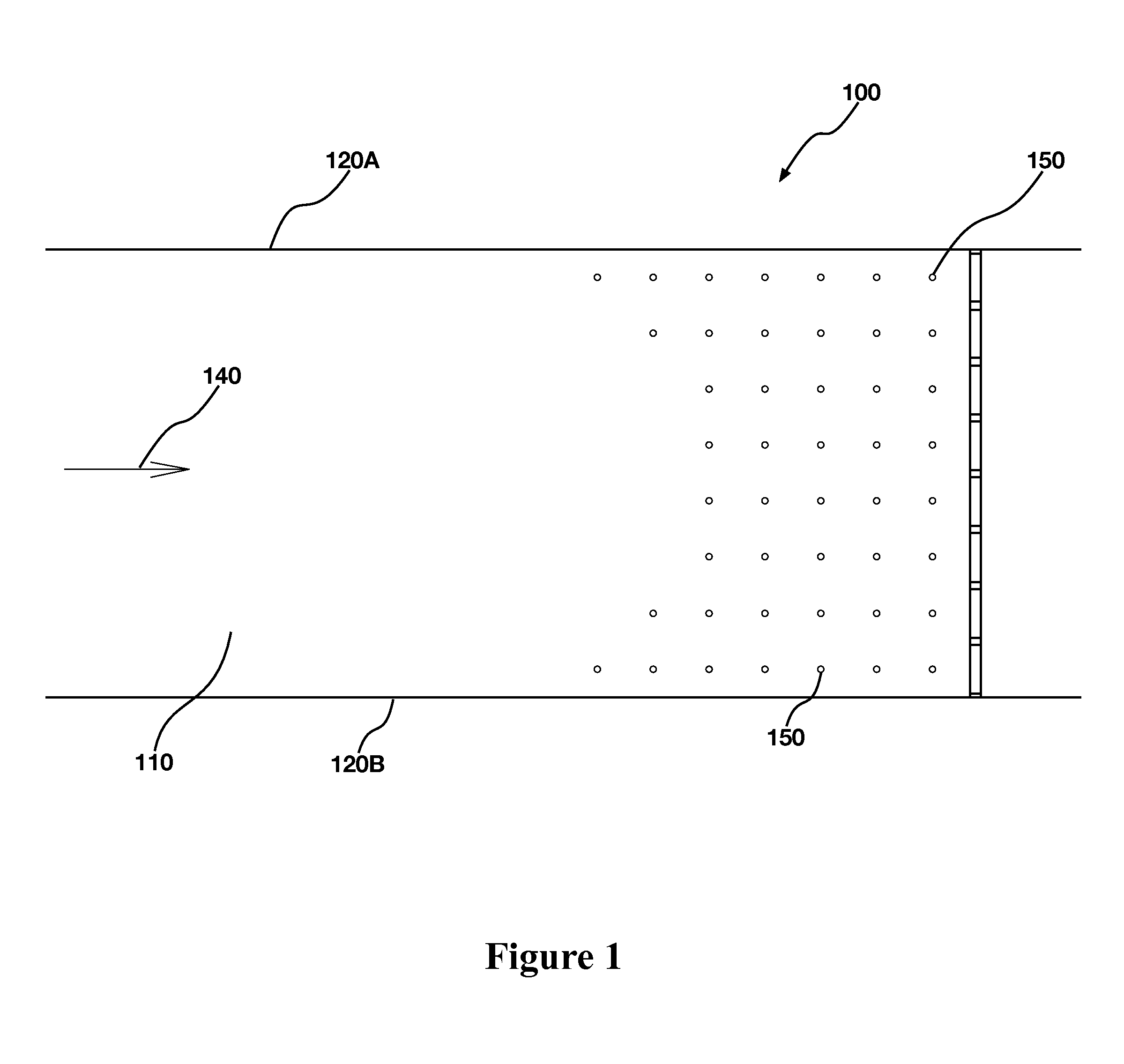
[0039]Now referring to FIG. 1 which depicts a top view of the electrode array installation 100. The electrode array installation 100 is placed in water channel 110 that is constrained by outer banks 120A, 120B. There is a flow 140 of water where the water 120 flows over individual electrodes 150 that are mounted on the bottom of the water channel 110.

[0040]In one embodiment, the water channel has dimensions of approximately 17 ½″ in width and the electrodes 150 are spaced approximately 30 inches apart.

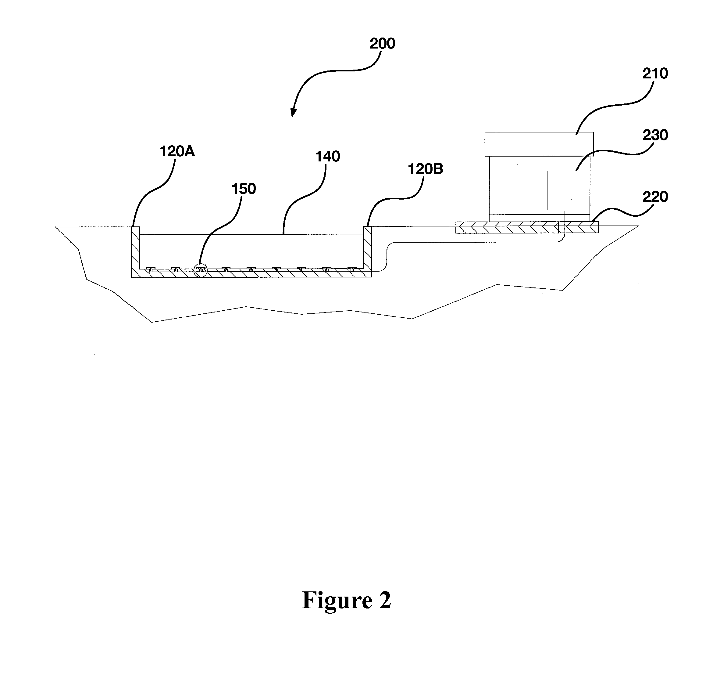
[0041]Now referring to FIG. 1 which depicts a top, cut-away (side), and detailed view of the matrix array electrical barrier. The top, cut-away (side), and close-up views of the barrier depicts a matrix array of electrodes embedded in an insulating concrete support structure. The electrode, in one embodiment, has a replaceable elect...


PUM


Abstract

Described herein is an aquatic electrical barrier that has the electrodes configured in a matrix array configuration, where each electrode element of the matrix array is mounted either directly on the bottom of a water channel or on extendable rods; the matrix array is controlled so that aquatic species may be physically moved by the aquatic species physiological response to a time-varying and spatially-varying electrical field.

Description

STATEMENT OF RELATED APPLICATIONS[0001]This application claims the benefit of U.S. provisional application No. 61 / 671,067, filed on Jul. 12, 2012, (Docket No. SRI 2.050.PR), the contents of which are herein incorporated into this application by reference.STATEMENT OF GOVERNMENT FUNDING[0002]No government funding was used in connection with this patent application.BACKGROUND[0003]1. Field of the Invention[0004]The inventive subject matter is directed towards the broad field of electrical water barriers to stun and repel fish in general and a unique matrix array electrode geometry.[0005]2. Background[0006]Electricity has been used to stun, capture, or modify the behavior of fish for more than one-hundred years. Various means of developing and controlling electric fields in water have been tried, with varying degrees of success.[0007]The effect of electric currents on fish are well known in the prior art and as described in the prior art of electrofishing. Electrofishing involves the u...

Claims


Application Information

Patent Timeline
IPC IPC(8): A01K79/02
CPCA01K79/02E02B1/006
Inventor CARSTENSEN, LEE ROYPARKIN, JOHN
Owner SMITH ROOT
Why Eureka
Try Eureka