
Filter bag assembly with rigid mesh for reducing filter pressure loss

a filter bag and rigid mesh technology, applied in the field of filters, can solve the problems of increased performance degradation, unforeseen shutdown, and insufficient air filters for certain environmental conditions, and achieve the effect of reducing filter pressure loss

Inactive Publication Date: 2015-07-23
BHA ALTAIR
View PDF7 Cites 10 Cited by
  • Summary
  • Abstract
  • Description
  • Claims
  • Application Information

AI Technical Summary

Benefits of technology

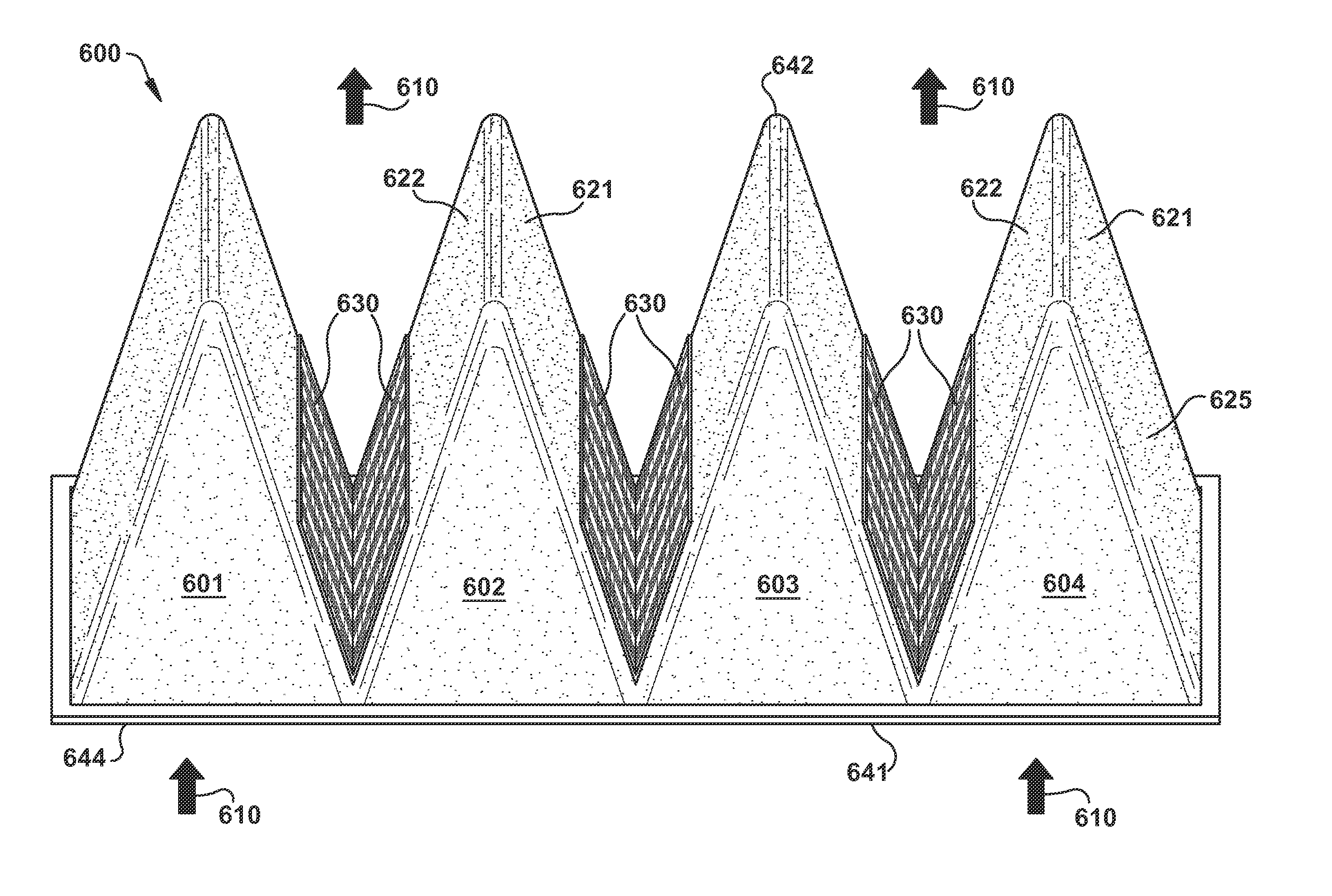
The present invention provides a filter bag assembly for removing particles from a fluid. The assembly includes two filter bags with tapered pockets. A substantially rigid mesh is in contact with the filter bags to maintain the shape of the tapered pockets and reduce filter pressure loss during use. The technical effects of this invention include improved filtration efficiency, reduced filter pressure loss, and improved quality of filtration.

Problems solved by technology

Unfortunately, existing air filters may be inadequate for certain environmental conditions, such as heavy fog, dust / sand storms, and other harsh conditions.
An inadequate air filter may cause operational problems for the turbine, such as, unforeseen shutdown or increased performance degradation.
Thus, under such harsh conditions, the installed air filter would require replacement with another more suitable air filter, thereby resulting in waste of the installed air filter.
When the pockets contact each other pressure loss is increased.
This is due to the fact that less filter media is available for air passage.
Shelves that extend from one pocket surface directly to an opposing pocket surface have been used to help support the pockets, but this approach suffers from the disadvantage that pre-filters cannot be used or nested with the primary filter.

Method used


Image

  • Filter bag assembly with rigid mesh for reducing filter pressure loss
  • Filter bag assembly with rigid mesh for reducing filter pressure loss
  • Filter bag assembly with rigid mesh for reducing filter pressure loss

Examples


Embodiment Construction

[0014]One or more specific embodiments of the present invention will be described below. In an effort to provide a concise description of these embodiments, all features of an actual implementation may not be described in the specification. It should be appreciated that in the development of any such actual implementation, as in any engineering or design project, numerous implementation-specific decisions must be made to achieve the developer's specific goals, such as compliance with system-related and business-related constraints, which may vary from one implementation to another. Moreover, it should be appreciated that such a development effort might be complex and time consuming, but would nevertheless be a routine undertaking of design, fabrication, and manufacture for those of ordinary skill having the benefit of this disclosure.

[0015]When introducing elements of various embodiments of the present invention, the articles “a”, “an” and “the” are intended to mean that there are o...


PUM

PropertyMeasurementUnit
Fractionaaaaaaaaaa
Fractionaaaaaaaaaa
Fractionaaaaaaaaaa

Abstract

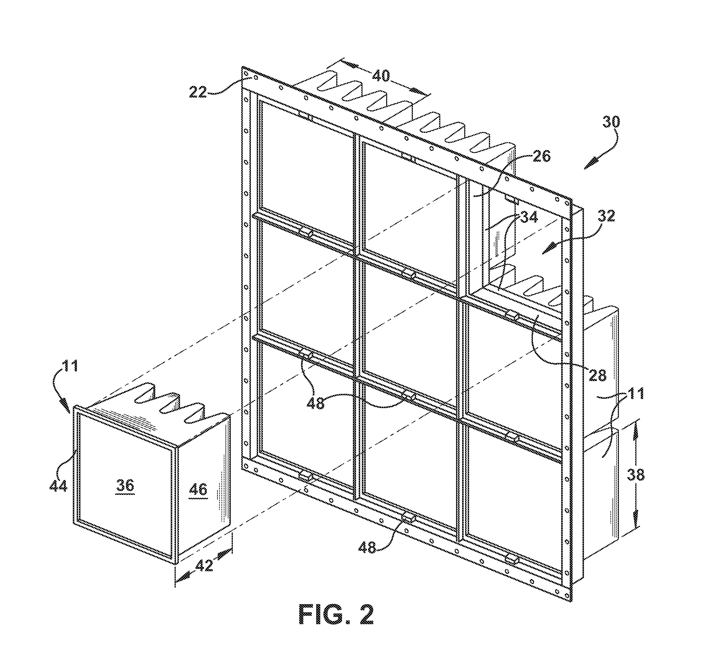
A filter bag assembly includes a first filter bag having at least two sidewalls of filter material extending from an open end to a closed end of the first filter bag at which the sidewalls connect to close the first filter bag. Two of the sidewalls of filter material are opposed to each other across the first filter bag and spaced from each other at the open end of the first filter bag. The two sidewalls are configured to form a tapered pocket, and the first filter bag includes a plurality of tapered pockets. A substantially rigid mesh is in contact with the first filter bag. The mesh is configured in a substantially V-shape and located near the open end of the first filter bag. The mesh is configured to maintain a shape of the tapered pockets and reduce filter pressure loss during use of the filter bag assembly.

Description

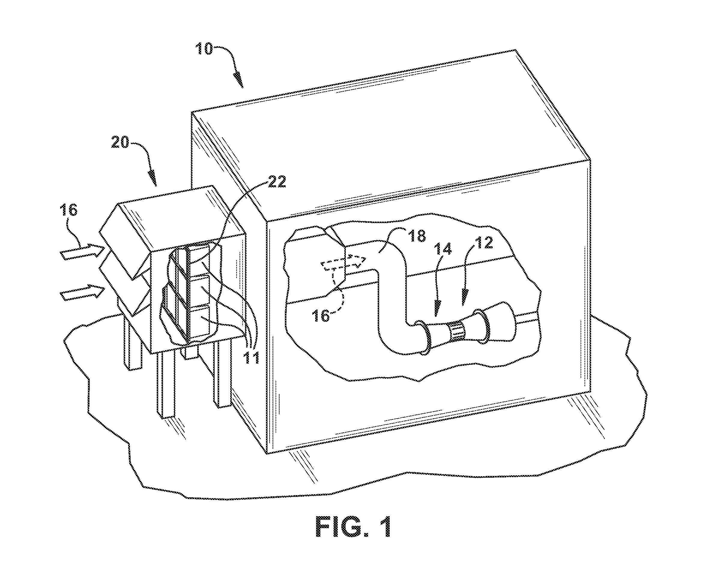
BACKGROUND OF THE INVENTION[0001]The subject matter disclosed herein relates to filters, and more particularly to reinforced filters that reduce pressure loss.[0002]A gas turbine engine combusts a fuel-air mixture to generate hot combustion gases, which drive rotation of turbine blades in a turbine section. The gas turbine engine may be used to drive an electrical generator or another load. The gas turbine engine intakes air through an air filter, which removes particulates to protect internal components of the gas turbine engine. Unfortunately, existing air filters may be inadequate for certain environmental conditions, such as heavy fog, dust / sand storms, and other harsh conditions. An inadequate air filter may cause operational problems for the turbine, such as, unforeseen shutdown or increased performance degradation. Thus, under such harsh conditions, the installed air filter would require replacement with another more suitable air filter, thereby resulting in waste of the inst...

Claims


Application Information

Patent Timeline
IPC IPC(8): B01D46/02
CPCB01D46/023
Inventor JARRIER, ETIENNE RENEPEMRICK, JAMES WARREN
Owner BHA ALTAIR
Learn More