Antenna device and electronic appliance

a technology of electronic appliances and antennas, applied in the direction of antennas, slot antennas, antenna details, etc., can solve the problems of limiting the design viewpoint, the inability to communicate with a communication partner, and the marked degrade of the communication range, so as to achieve the effect of ensuring the communication performan

Active Publication Date: 2015-07-23
MURATA MFG CO LTD
View PDF1 Cites 16 Cited by
  • Summary
  • Abstract
  • Description
  • Claims
  • Application Information

AI Technical Summary

Benefits of technology

[0018]With various preferred embodiments of the present invention, communication performance is secured wh

Problems solved by technology

However, in an electronic appliance that includes a metal casing, there are problems in that it becomes impossible to perform communication with a communication partner or the communication range is markedly degraded

Method used


Image

  • Antenna device and electronic appliance
  • Antenna device and electronic appliance
  • Antenna device and electronic appliance

Examples


first preferred embodiment

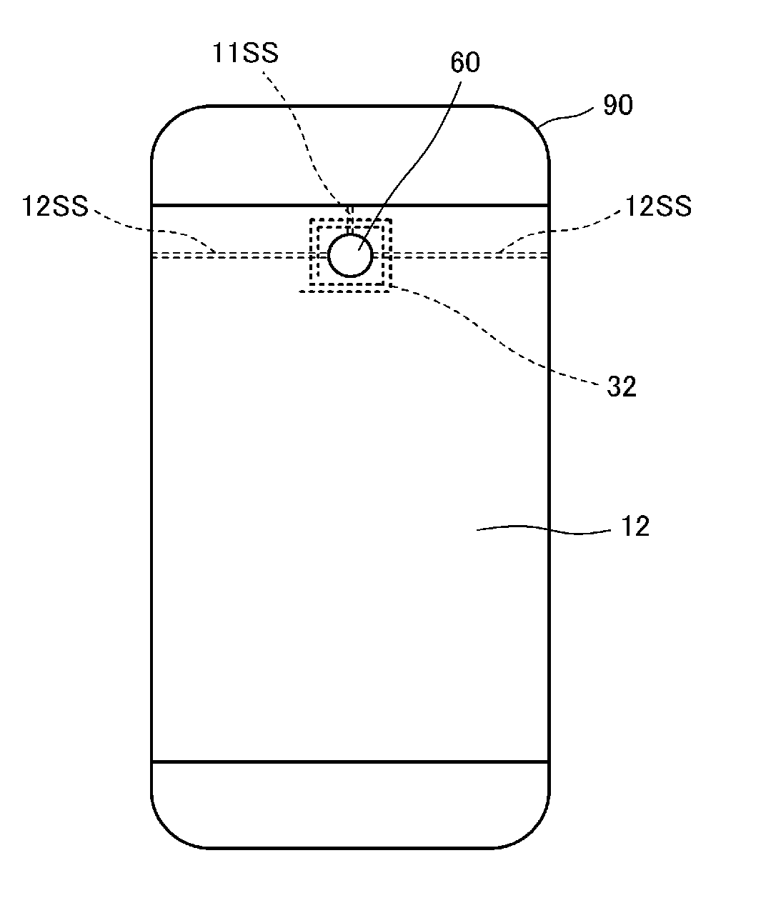
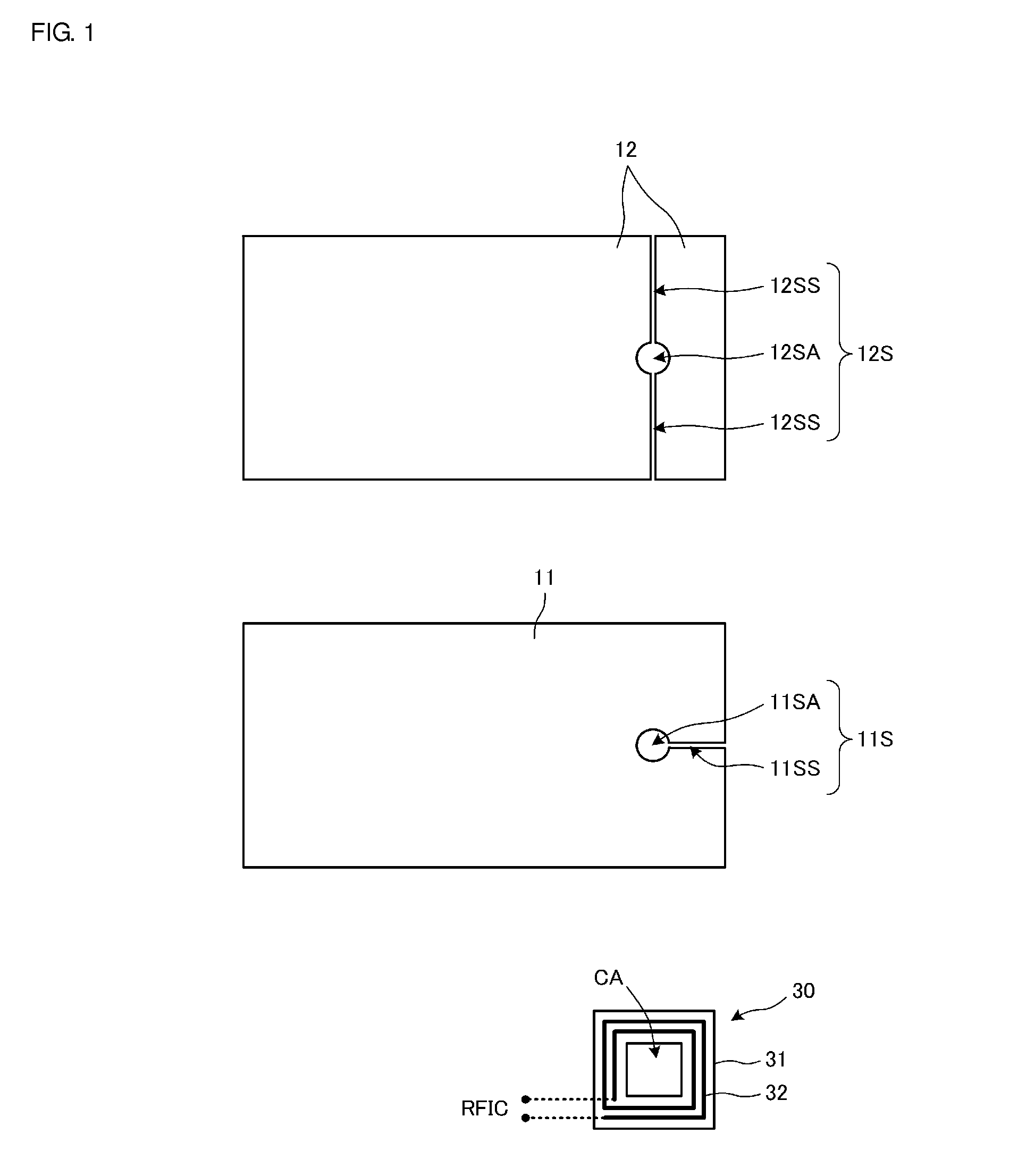
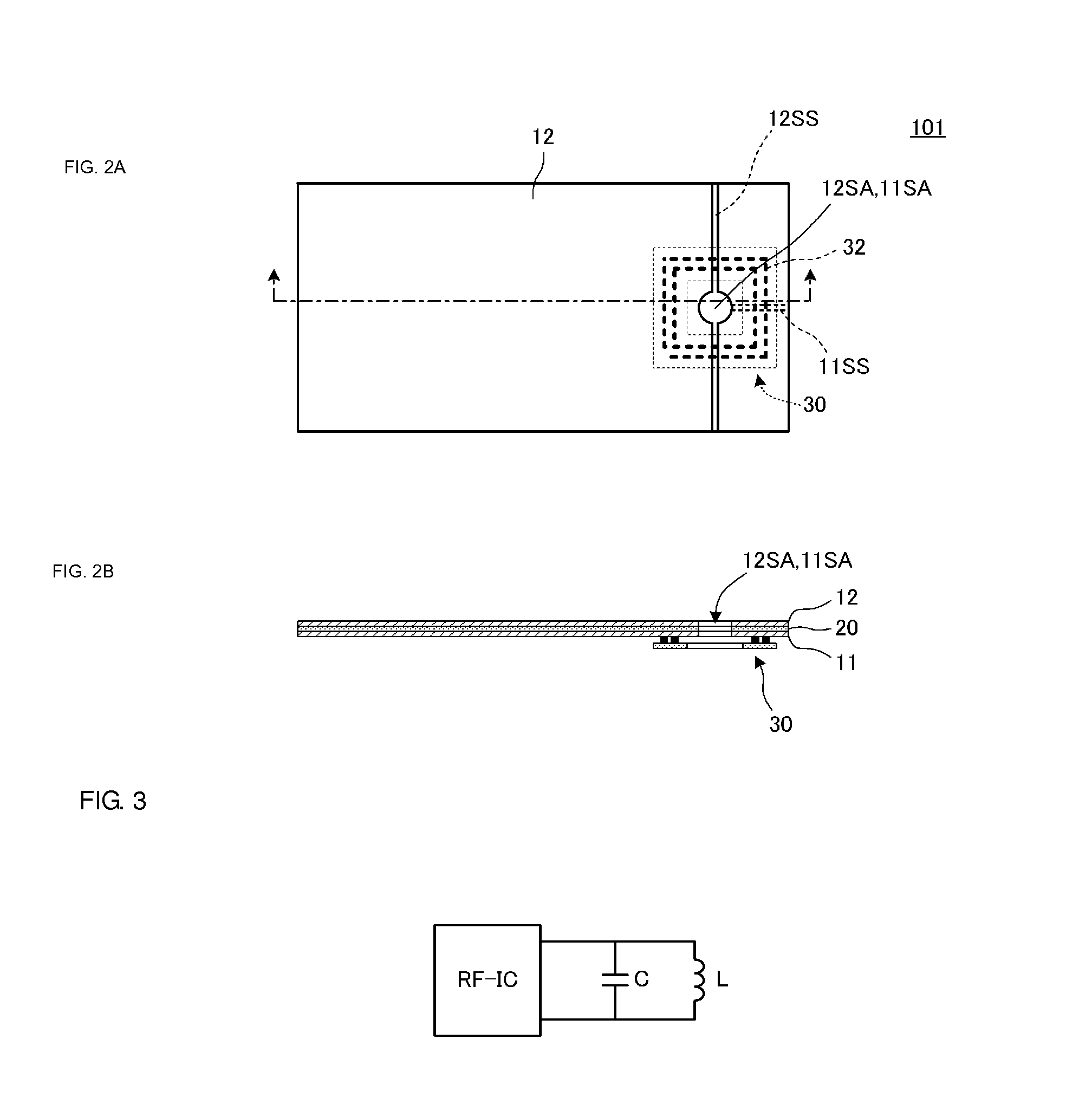
[0036]FIG. 1 is a plan view in which constituent elements of an antenna device of a first preferred embodiment of the present invention are illustrated in an arrayed manner spaced apart from one another. FIG. 2A is a plan view of this antenna device 101 and FIG. 2B is a sectional view of the antenna device 101.

[0037]The antenna device 101 includes a feeder coil 30, which is connected to a feeder circuit, a first conductor surface 11 and a second conductor surface 12. The feeder coil 30 includes a magnetic sheet 31 and a coil conductor 32. The coil conductor 32 is configured as a coil pattern on a flexible substrate, which is not illustrated. The flexible substrate is adhered to the magnetic sheet 31. An opening CA is provided in the center of the magnetic sheet 31 and the coil conductor 32 is configured so as to be wound around the opening CA in a spiral shape. That is, the opening CA is an opening in the magnetic sheet 31 and is a coil opening. An RFIC is connected to the two ends ...

second preferred embodiment

[0050]FIG. 6 is an exploded perspective view of an antenna device 102 of a second preferred embodiment of the present invention. This antenna device differs from the antenna device of the first preferred embodiment illustrated in FIG. 4 in that the first conductor surface 11 and the second conductor surface are electrically (DC) conductive with each other through conductor surface connection conductors 21A, 21B, 21C, 21D, 21E and 21F at a plurality of positions. In addition, in this preferred embodiment, the opening portion 11SA provided in the first conductor surface 11 and the opening portion 12SA formed in the second conductor surface 12 have a rectangular or substantially rectangular shape in accordance with the shape of the coil conductor 32 of the feeder coil 30.

[0051]The first conductor surface 11 and the second conductor surface 12 are made to be conductive with each other via the conductor surface connection conductors 21A to 21F at a plurality of positions, such that the e...

third preferred embodiment

[0054]FIG. 7 is an exploded perspective view of an antenna device 103 of a third preferred embodiment of the present invention. The antenna device 103 includes a display 40 formed of a liquid crystal display panel equipped with a touch panel and a display surface of this display 40 acts as a communication surface. This display 40 corresponds to a “flat panel display” of various preferred embodiments of the present invention. The basic configurations of the feeder coil 30, the first conductor surface 11 and the second conductor surface 12 preferably are the same as those described in the first and second preferred embodiments. The second conductor surface 12 and the first conductor surface 11 are adhered to a rear surface of the display 40 and these elements are integrated with each other. The antenna device 103 is provided of this multilayer body and the feeder coil 30.

[0055]Transparent electrodes (ITO) are provided in the liquid crystal display panel and the touch panel of the disp...


PUM


Abstract

An antenna device includes a feeder coil connected to a feeder circuit, a first conductor surface including a first slit that extends in a direction toward an outer edge and a second conductor surface including a second slit that extends in a direction toward an outer edge. The feeder coil is arranged at a position that is superposed with the first slit when viewed in plan, the feeder coil and the first conductor surface are magnetically coupled with each other, the first conductor surface and the second conductor surface are magnetically coupled with each other and the first slit and the second slit are arranged at positions so as to be partially superposed with each other when viewed in plan. At least a portion of the first slit is superposed with a portion of the second conductor surface other than the second slit when viewed in plan, and at least portion of the second slit is superposed with a portion of the first conductor surface other than the first slit when viewed in plan.

Description

BACKGROUND OF THE INVENTION[0001]1. Field of the Invention[0002]The present invention relates to antenna devices preferably for use in near field communication (NFC) systems and so forth and to electronic appliances equipped with such an antenna device.[0003]2. Description of the Related Art[0004]In mobile communication appliances such as cellular phone terminals and tablet PCs, mounting of communication circuits corresponding to HF band communication systems such as an NFC system has been progressing.[0005]In addition, profile reduction has also been progressing in recent mobile communication appliances and it has become increasingly common to reinforce the strength of such appliances through “metallization” of the casing by, for example, performing a magnesium plating treatment on a resin casing or using a metal casing such as an aluminum body in order to deal with strength deficiencies caused by such profile reduction.[0006]However, in an electronic appliance that includes a meta...

Claims


Application Information

Patent Timeline
IPC IPC(8): H01Q1/52H01Q7/06H01Q1/24
CPCH01Q1/526H01Q7/06H01Q1/243H01Q13/10
Inventor NAKANO, SHINICHI
Owner MURATA MFG CO LTD
Why Eureka
Try Eureka