Superconducting power generation system and associated method for generating power

a superconducting power generation and superconducting bulb technology, applied in windings, mechanical energy handling, magnetic circuit shapes/forms/construction, etc., can solve the problems of low torque density of conventional direct drive generators, unsuitable hydro turbine applications, unreliable gear boxes,

Inactive Publication Date: 2015-07-23
GENERAL ELECTRIC CO
View PDF7 Cites 2 Cited by
  • Summary
  • Abstract
  • Description
  • Claims
  • Application Information

AI Technical Summary

Problems solved by technology

However, conventional direct drive generators typically have low torque density and are too heavy for the hydro turbine.
However, such gear boxes tend to be unreliable and not suitable in a hydro application.

Method used


Image

  • Superconducting power generation system and associated method for generating power
  • Superconducting power generation system and associated method for generating power
  • Superconducting power generation system and associated method for generating power

Examples


Embodiment Construction

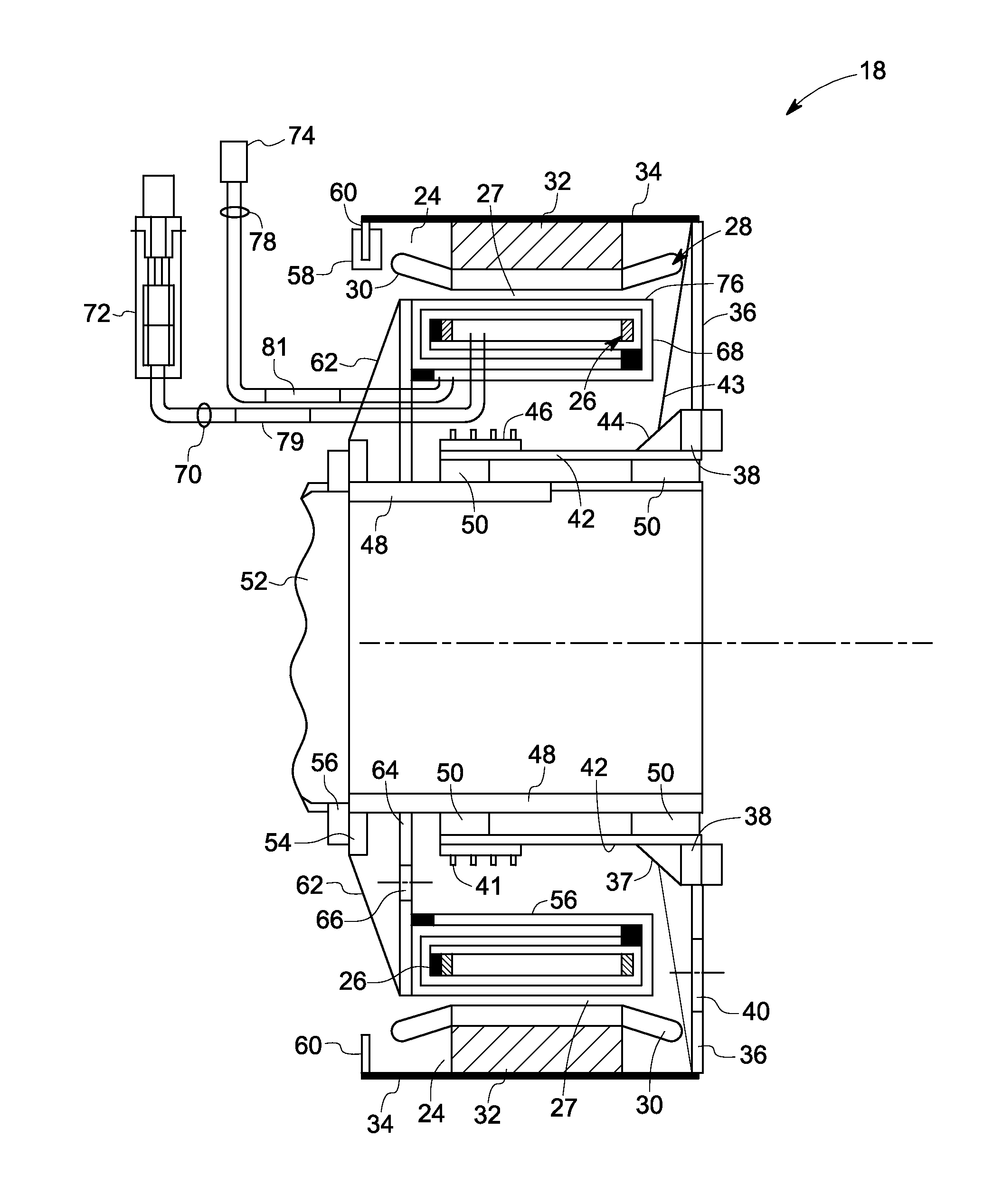
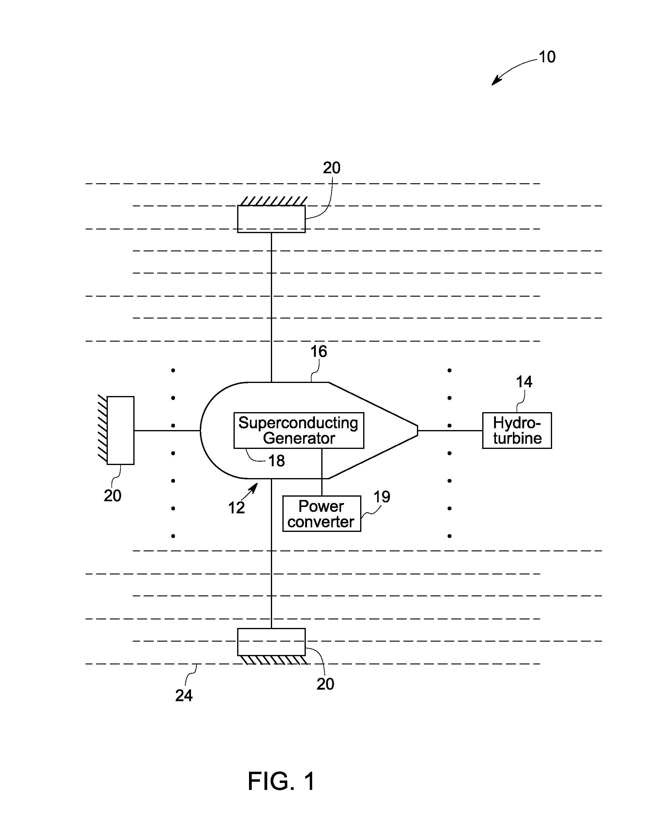
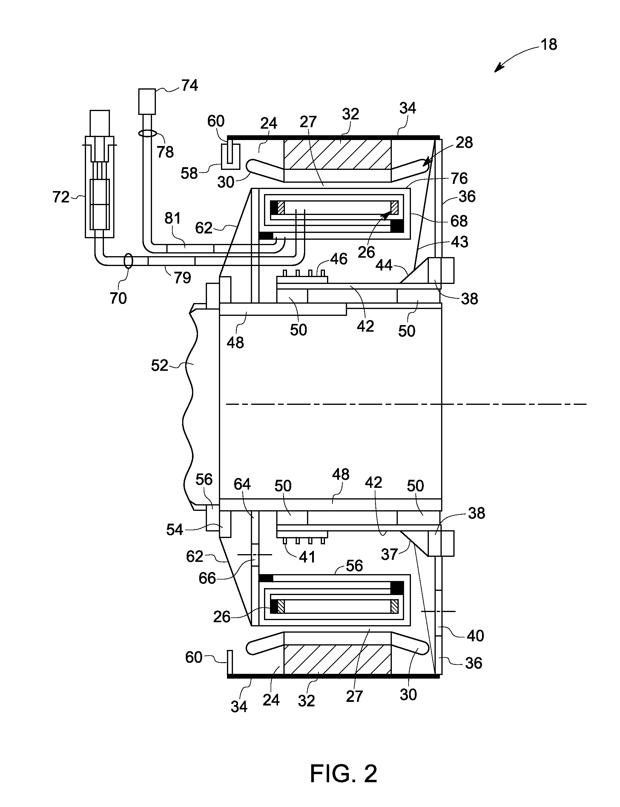
[0015]Embodiments of the present invention disclose a superconducting bulb hydro machine and a method of generating electric power via the superconducting bulb hydro machine. The superconducting bulb hydro machine includes a generator unit coupled to a hydro turbine. The generator unit includes a superconducting generator disposed within a casing. The casing has a first stationary support coupleable to a base disposed within water. The superconducting generator includes an annular field winding having a plurality of superconducting magnets disposed coaxial with an annular armature and separated by a gap. One of the annular armature and the annular field winding is rotatable by the hydro turbine and other of the annular armature and the annular field winding is stationary.

[0016]FIG. 1 is a diagrammatical representation of a system 10 i.e. a superconducting bulb hydro machine, in accordance with an exemplary embodiment of the present invention. The system 10 includes a generator unit ...


PUM


Abstract

A system includes a generator unit coupleable to a hydro turbine. The generator unit includes a casing having a first stationary support coupleable to a base disposed within water and a superconducting generator disposed within the casing. The superconducting generator includes an annular armature and an annular field winding including a plurality of superconducting magnets disposed coaxial with the annular armature and separated by a gap. One of the annular armature and the annular field winding is rotatable by the hydro turbine and other of the annular armature and the annular field winding is stationary.

Description

BACKGROUND[0001]The invention relates generally to electric power generation systems, and, more particularly, to a superconducting bulb hydro machine used for generating electric power.[0002]A direct drive generator driven by a plurality of blades of a hydro turbine is efficient and has minimal losses due to transmission of torque from the plurality of turbine blades to the generator. However, conventional direct drive generators typically have low torque density and are too heavy for the hydro turbine. Use of indirect drive generators, which usually include a gearbox and a shaft, results in a compact high speed generator. However, such gear boxes tend to be unreliable and not suitable in a hydro application.[0003]There is a need for an enhanced direct drive generator for hydro turbines that is reliable, light weight, and capable of generating electrical power.BRIEF DESCRIPTION[0004]In accordance with one exemplary embodiment, a system is disclosed. The system includes a generator u...

Claims


Application Information

Patent Timeline
Patent Type & Authority Applications(United States)
IPC IPC(8): H02K1/06H02K9/20
CPCH02K9/20H02K1/06H02K55/04H02K7/1823Y02E40/60
Inventor HARAN, KIRUBA SIVASUBRAMANIAMSTAUTNER, ERNST WOLFGANGROCHFORD, JAMES HUMPHRIEROCKHILL, ANDREW ALLENFAIR, RUBEN JEEVANASANRAJPUT-GHOSHAL, RENUKA
Owner GENERAL ELECTRIC CO
Why Eureka
Try Eureka