Contactless power supply system and contactless extension plug

a technology of contactless power supply and extension plug, which is applied in the direction of transformer/inductance circuit, circuit arrangement, inductance, etc., can solve the problems of not proposing specific structure or design, limit the applicable range when control is performed only at the power supply device side, etc., and achieve the effect of easy generation of load voltag

Active Publication Date: 2015-07-30
PANASONIC INTELLECTUAL PROPERTY MANAGEMENT CO LTD
View PDF1 Cites 19 Cited by
  • Summary
  • Abstract
  • Description
  • Claims
  • Application Information

AI Technical Summary

Benefits of technology

[0029]In a contactless power supplying system using a magnetic coupling coil and a resonance capacitor, the present

Problems solved by technology

However, in a contactless power supply system that adapts a single power supplying device to a plurality of power receiving devices that generate different output voltages like in patent document 1, when load voltage values greatly differ

Method used


Image

  • Contactless power supply system and contactless extension plug
  • Contactless power supply system and contactless extension plug
  • Contactless power supply system and contactless extension plug

Examples


first embodiment

[0048]A contactless power supply system of a first embodiment will be hereinafter described according to the drawings.

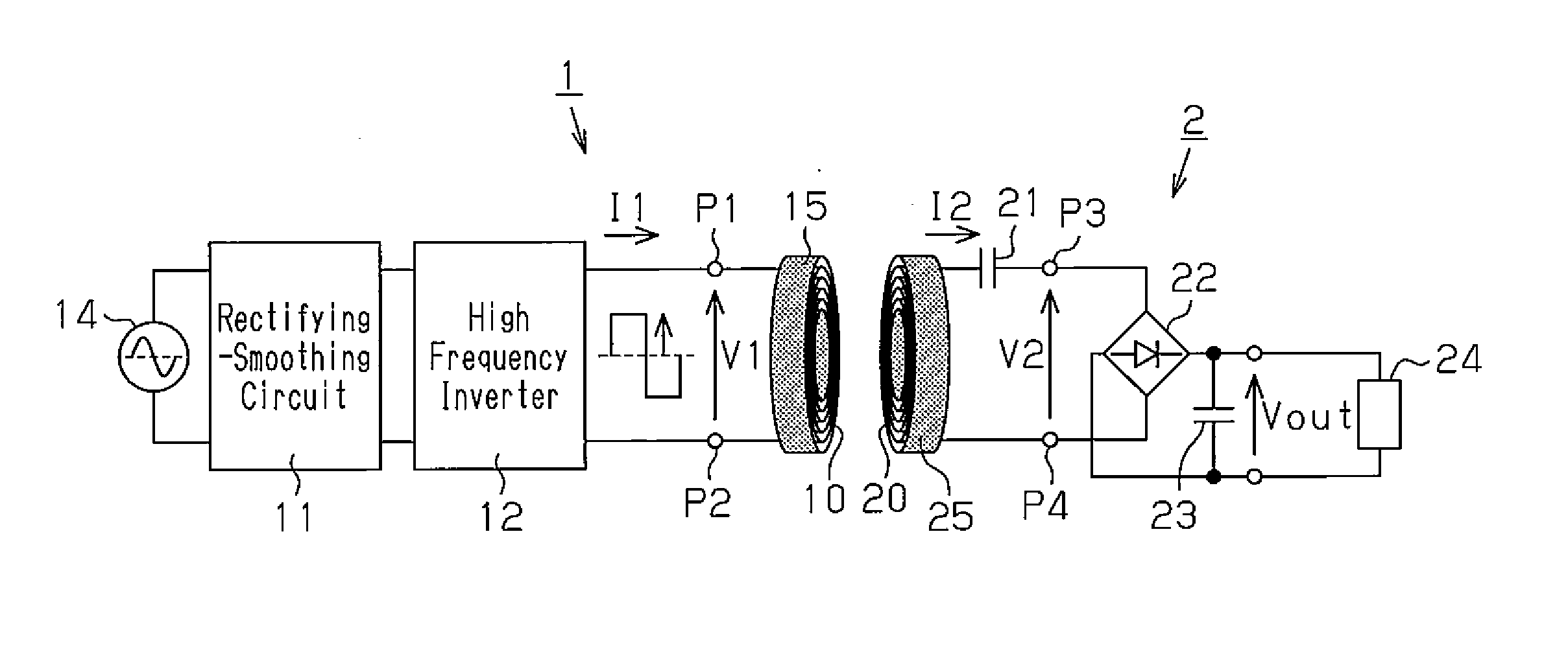
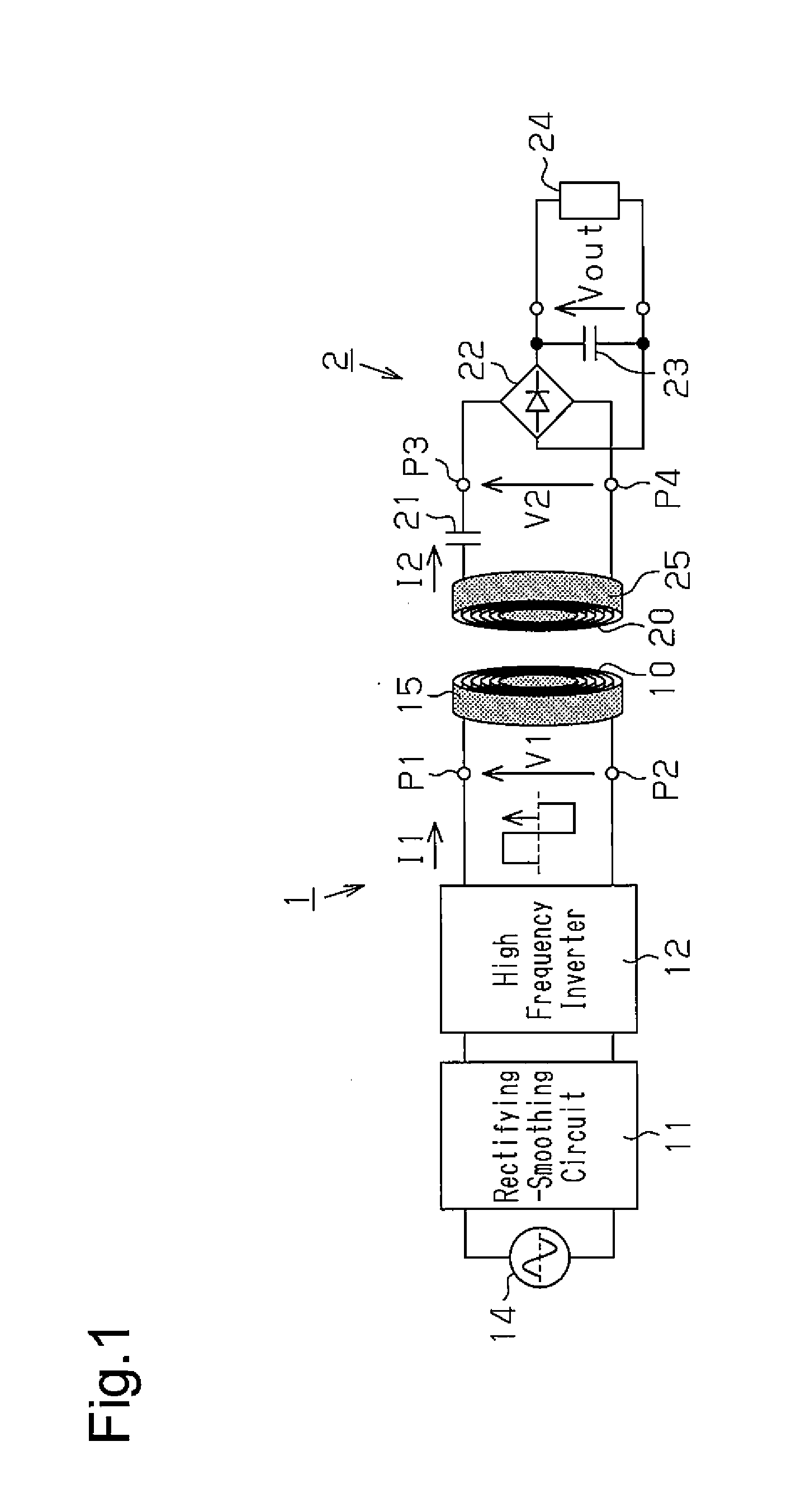
[0049]FIG. 1 is a diagram showing a schematic electrical circuit diagram of a contactless power supply system. In FIG. 1, the contactless power supply system includes a power supplying device 1, and a power receiving device 2 serving as an electrical appliance.

[0050]The power supplying device 1 includes a power transmission coil 10, a rectifying-smoothing circuit 11, and a high frequency inverter 12. The rectifying-smoothing circuit 11, which includes a full-wave rectifying circuit and a smoothing capacitor, rectifies a commercial AC power supply 14 to a DC voltage with the full-wave rectifying circuit, smoothens the DC voltage with the smoothing capacitor, and outputs the DC voltage to the high frequency inverter 12.

[0051]The high frequency inverter 12 is a known half-bridge type or a full-bridge type inverter, for example, and generates a high frequency voltage (pr...

second embodiment

[0112]A second embodiment of a contactless power supply system will now be described.

[0113]In the contactless power supply system of the second embodiment shown in FIG. 4, two contactless extension plugs, that is, a first contactless extension plug 3 and a second contactless extension plug 4 are located between the power supplying device 1 and the power receiving device 2 described in the first embodiment.

[0114]The first contactless extension plug 3 includes a first plug power reception coil 30, a first plug power transmission coil 31, and a first plug resonance capacitor 32.

[0115]The first plug power reception coil 30 is arranged to face the power transmission coil 10 of the power supplying device 1 so as to be magnetically coupled thereto, and interlinks with the alternating magnetic field generated by the power transmission coil 10 and outputs the induced electromotive force. The first plug power reception coil 30 is wound around a third pot type core 33 having the same shape and...

third embodiment

[0143]A third embodiment of a contactless power supply system will now be described.

[0144]In the third embodiment, an example in which one contactless extension plug described in the second embodiment is used will be described. For the sake of convenience, description will be made assuming the contactless extension plug of the third embodiment is the first contactless extension plug 3, and the same reference characters and the like will be used in the third embodiment.

[0145]As shown in FIG. 8, a power transmission outlet 51 and a power reception outlet 52 are arranged on both sides of a thick wall 50. The power supplying device 1 and the power receiving device 2 are arranged with a wall 50 in between.

[0146]The power supplying device 1 includes a power supplying plug 55 formed by winding the power transmission coil 10 around the first pot type core 15. The power supplying plug 55 is attached in a removable manner to the power transmission outlet 51.

[0147]The power receiving device 2 ...


PUM


Abstract

A contactless power supply system includes a first power transmission coil, a plug power reception coil, a plug power transmission coil, and a first power reception coil. The first power transmission coil and the plug power reception coil are configured to satisfy a relational equation of (L2a/L1)1/2=G1/K1=N2a/N1, where L1 represents a self-inductance of the first power transmission coil, L2a represents a self-inductance of the plug power reception coil, N1 represents a winding number of the first power transmission coil, N2a represents a winding number of the plug power reception coil, K1 represents a coupling coefficient of the first power transmission coil and the plug power reception coil, and G1 represents a voltage conversion gain of the voltage applied to the plug power transmission coil relative to the voltage applied to the first power transmission coil.

Description

TECHNICAL FIELD[0001]The present invention relates to a contactless power supply system and a contactless extension plug.BACKGROUND ART[0002]Generally, a contactless power supply system is formed by a power supplying device, which includes a power transmission coil, and a power receiving device, which includes a power reception coil. The power supplying device generates high frequency current and sends the high frequency current to the power transmission coil to generate an alternating magnetic field at the power transmission coil. The power receiving device interlinks the alternating magnetic field generated by the power transmission coil of the power supplying device with the power reception coil, which faces the power transmission coil, so that the power reception coil generates an induced electromotive force. The power receiving device rectifies the induced electromotive force generated by the power reception coil to generate direct current (DC) voltage and supply the DC voltage...

Claims


Application Information

Patent Timeline
IPC IPC(8): H02J5/00
CPCH02J5/005H01F38/14H02J50/12H02J50/50H02J50/70H02J50/005H02J50/10
Inventor ABE, HIDEAKI
Owner PANASONIC INTELLECTUAL PROPERTY MANAGEMENT CO LTD
Why Eureka
Try Eureka