Sunshades with Solar Power Supplies for Charging Electronic Devices

a technology of solar power supply and solar panel, which is applied in the field of sunshades with solar power supply for charging electronic devices, outdoor furniture, etc., can solve the problems of inability to charge more than one device at a time, limited storage capacity of battery packs, and power loss of portable electronic devices used outdoors

Active Publication Date: 2015-08-06
LEGACY CONSULTING LLC
View PDF5 Cites 93 Cited by
  • Summary
  • Abstract
  • Description
  • Claims
  • Application Information

AI Technical Summary

Benefits of technology

[0083]According to another specific implementation, the method includes coupling a battery-charging controller between the solar panels and the rechargeable battery, such that fluctuations in electrical power received from the solar panels at the battery-charging controller do not affect the current provided from the rechargeable battery to the first or the second charging ports.
[0118]Another advantage is the ability to provide a mobile supply of electricity to users because elements of the system (i.e., solar panel, battery, ports, and connector) are integrated into the sunshades and furniture. A user need not depend on an electrical outlet for electrical power because there is battery storage within the sunshade or furniture itself. As a result, a user can change location outdoors throughout the day while maintaining a continuous supply of electrical power. For example, a user can charge a smartphone using a portable, detachable sunshade for a lounge chair on the beach. The phone can continue to charge from the reserve battery power even after the sunshade is detached from the lounge chair, and while it is moved to a different lounge chair.

Problems solved by technology

Since users often spend up to several hours using outdoor furniture while partaking in outdoor activities, the portable electronic device (e.g., mobile phones, tablet computers, personal digital assistants, portable music players, or portable televisions) that users use outdoors may run out of power and need to be charged.
Battery packs are often not designed to charge larger devices, such as tablet computers, and often are not capable of charging more than one device at a time.
Furthermore, battery packs have a limited amount of stored power.
Running a power line from a main power source to where users are at outdoors is often not possible where no power supply exists or is not practical where no power supply is reasonably close.

Method used


Image

  • Sunshades with Solar Power Supplies for Charging Electronic Devices
  • Sunshades with Solar Power Supplies for Charging Electronic Devices
  • Sunshades with Solar Power Supplies for Charging Electronic Devices

Examples


Embodiment Construction

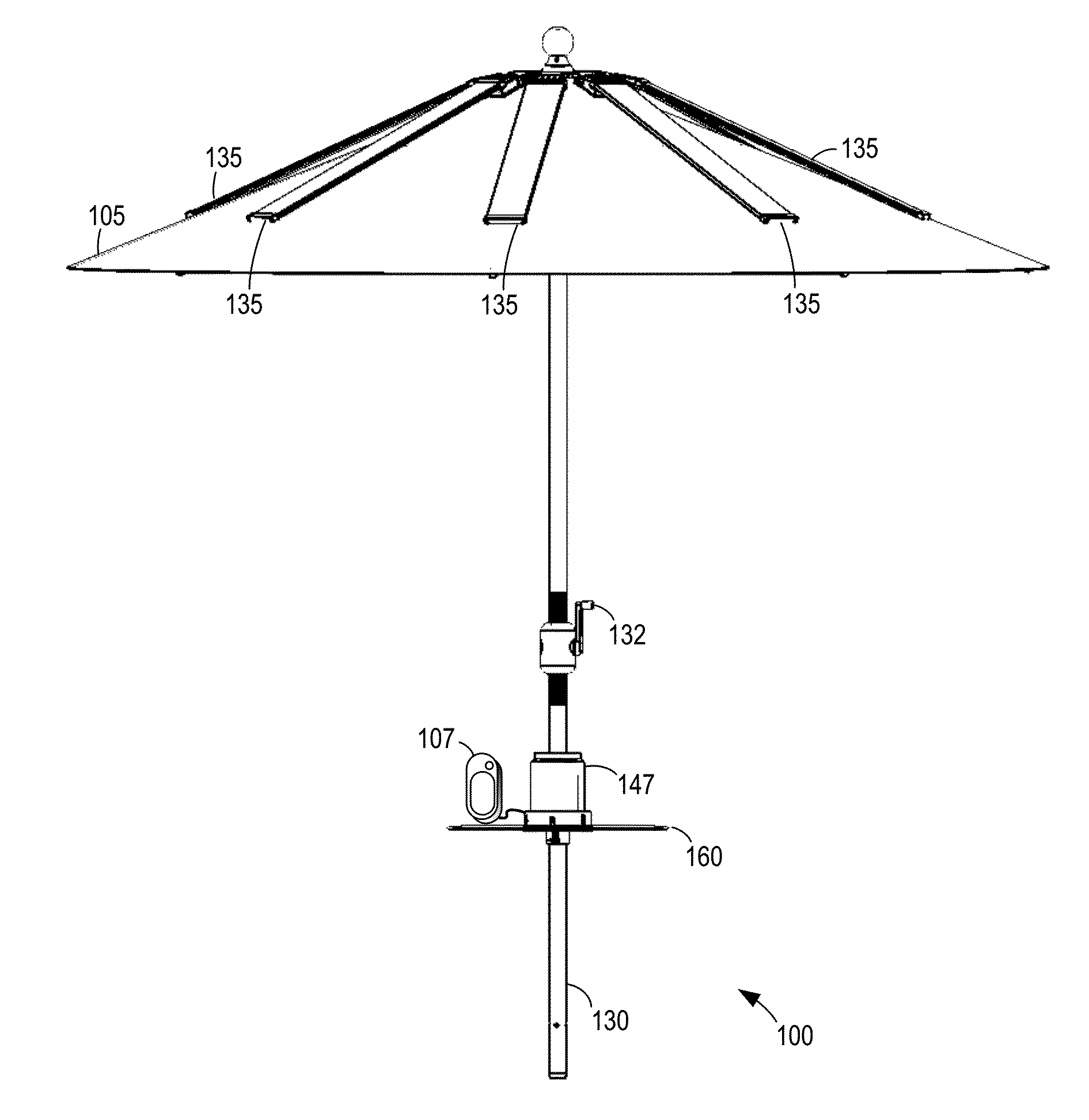
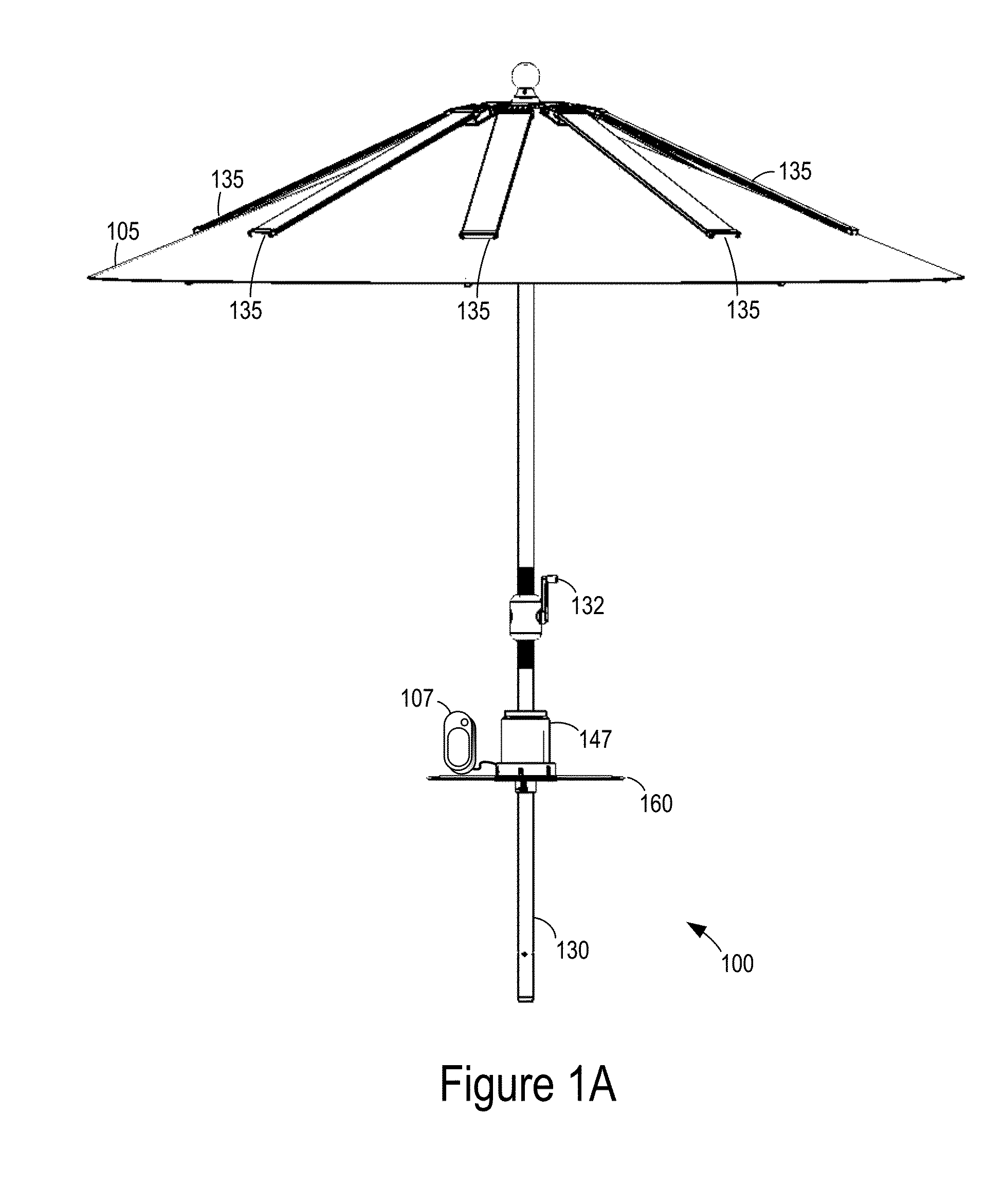
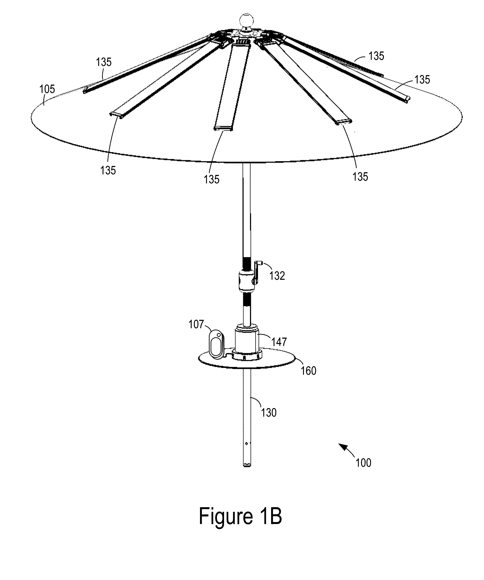
[0161]FIGS. 1A, 1B, and 1C respectively show a front view, a perspective view, and an underside view of an umbrella 100 according to one implementation. FIG. 1D shows a further enlarged underside view of umbrella 100. Umbrella 100 is configured to protect a user from light (e.g., sunlight), collect the light, then convert the light into electricity, and use the electricity to power or charge one or more connected portable electronic devices 107. Light collection, conversion, and charging are described further below after various mechanical elements of umbrella 100 are described.

[0162]In one implementation, umbrella 100 includes a shade 105, a number of struts 110 (e.g., 8 struts), a number of ribs 115 (e.g., 8 ribs or spines), a first hub 120, and a second hub 125. Umbrella 100 also includes an umbrella pole 130 (sometimes referred to as an umbrella spine or spine) that holds the umbrella upright when in use. The umbrella pole can be aluminum, steel, wood, carbon fiber, or other mat...


PUM

PropertyMeasurementUnit
DC voltageaaaaaaaaaa
poweraaaaaaaaaa
diameteraaaaaaaaaa

Abstract

A device includes a frame structure; a shade attached to the frame structure; and a pole attached to the frame structure. The device includes a solar panel attached to the frame structure and positioned above the shade. The frame and the shade unfold upward along the pole to open the shade. The solar panel rotates up as the frame and shade unfold upward. The frame and the shade fold down along the pole to close the shade. The solar panel rotates down as the frame and shade fold down.

Description

CROSS-REFERENCE TO RELATED APPLICATIONS[0001]This patent application claims the benefit of U.S. provisional patent applications 61 / 924,186, filed Jan. 6, 2014 and 62 / 041,573, filed Aug. 25, 2014, and is a continuation-in-part of the following U.S. design patent application Ser. No. 29 / 487,288, filed Apr. 7, 2014; Ser. No. 29 / 499,274, filed Aug. 13, 2014; and Ser. No. 29 / 502,277, filed Sep. 12, 2014, which are incorporated by reference along with all other references cited in these applications.BACKGROUND[0002]The present invention generally relates to furniture. More particularly, implementations of the present invention provide outdoor furniture having integrated solar panels for powering and charging portable electronic devices.[0003]Outdoor furniture is a type of furniture that is often used during daylight hours to provide comfortable outdoor seating, to shade users from the sun, or both. Outdoor furniture is commonly set up, for example, by swimming pools, on beaches, on patios...

Claims


Application Information

Patent Timeline
Patent Type & Authority Applications(United States)
IPC IPC(8): A45B25/00H02S20/30B23P15/26
CPCA45B25/00B23P15/26H02S20/30A45B2025/003H02J7/0047A45B3/04A45B25/02A45B2200/1018A45B2200/1027H02J7/35A45B3/00A45B2023/0012A45B2023/0037A45B2200/1054A45B2200/1063A45B2200/109H01L31/042H02S30/20Y02E10/50Y10T29/49004Y10T29/49117Y10T29/49169Y10T29/49355Y10T29/4984H02J7/00045H02J7/0048H02J7/0045H02J2310/22H02J50/12H02J50/80H02J7/00H02J7/0013A45B23/00
Inventor AKIN, SARAHJOHNSON, DAVID
Owner LEGACY CONSULTING LLC
Why Eureka
Try Eureka