
Endotracheal tube connector positioning system and method

a positioning system and endotracheal tube technology, applied in the field of medical devices, can solve the problems of brain damage or death, insufficient airflow, and endotracheal tube dislocation from its proper position in the trachea, and achieve the effect of minimizing the manipulation of the endotracheal tub

Inactive Publication Date: 2015-08-06
SICHAU GARY STEVEN +1
View PDF11 Cites 1 Cited by
  • Summary
  • Abstract
  • Description
  • Claims
  • Application Information

AI Technical Summary

Benefits of technology

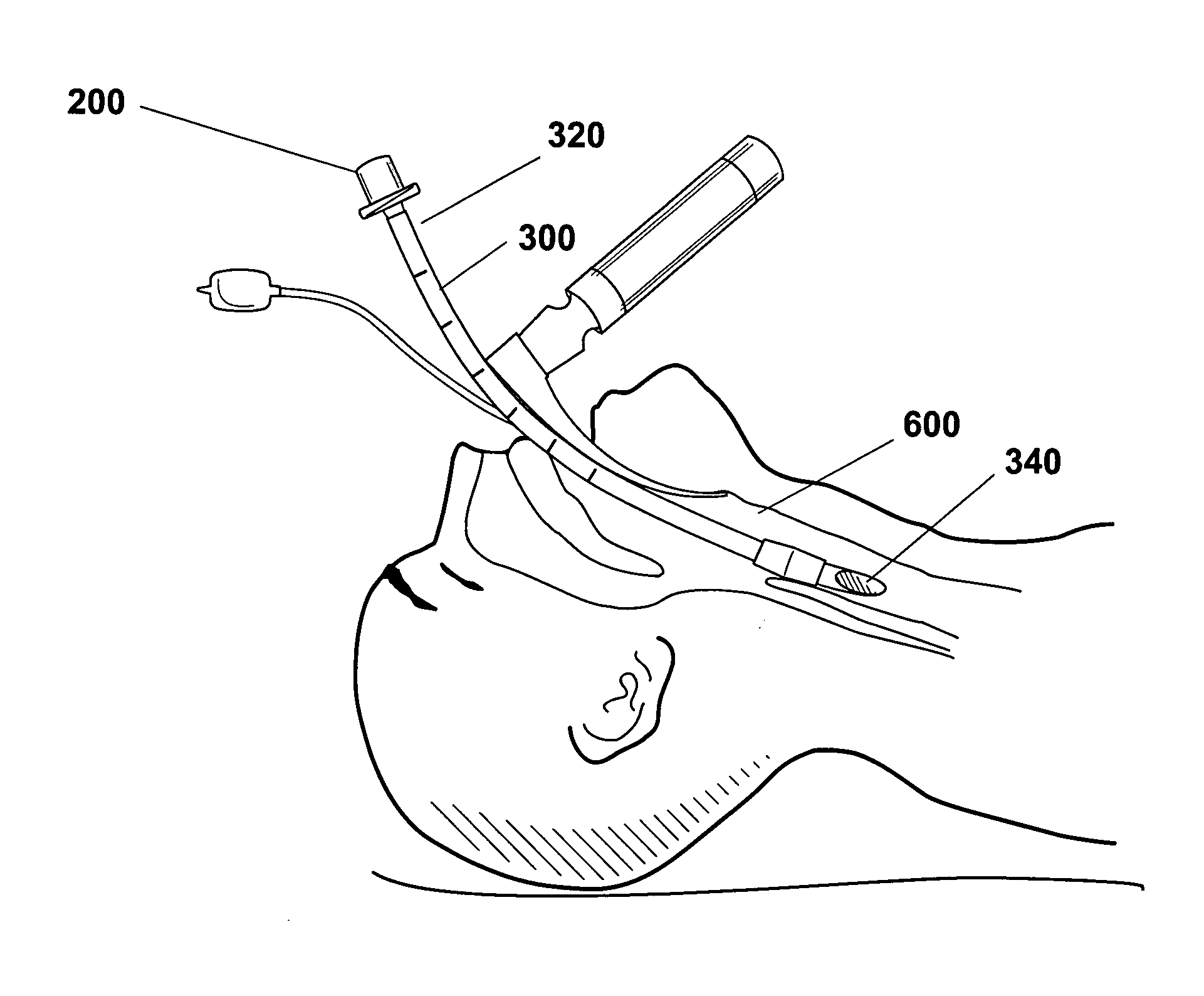
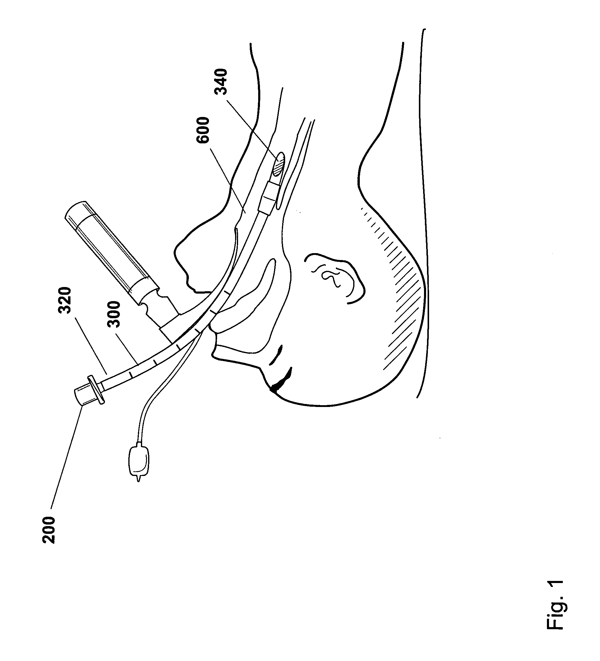
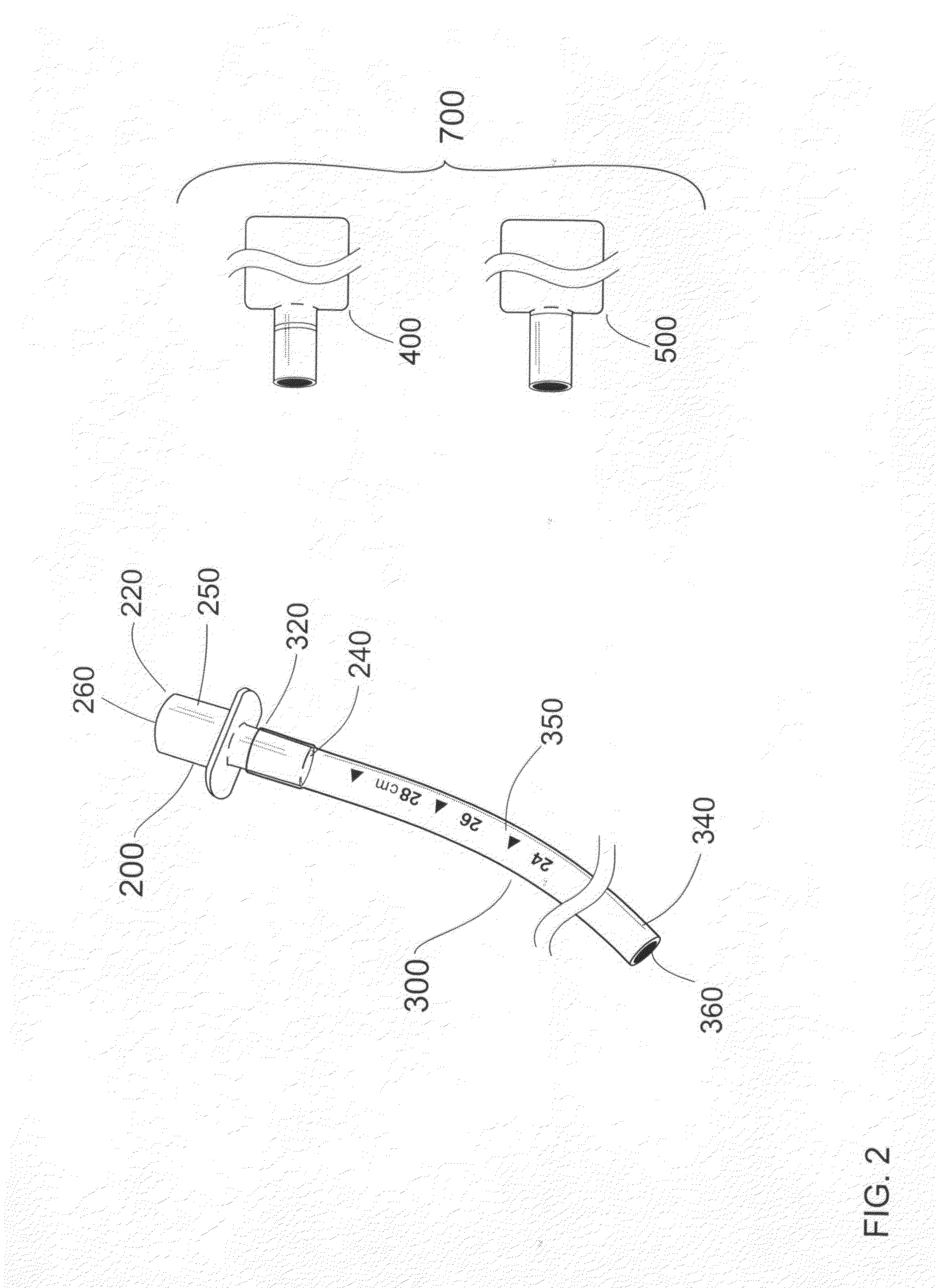
The patent describes a mechanism and method for reliably assessing the presence of carbon-dioxide gas and providing continuous feedback on whether the endotracheal tube is correctly positioned within the patient's airway to ensure proper ventilation, without the need for reattaching and detaching a carbon-dioxide sensing device. The detection system operates as a part of the ventilation circuit, minimizing the manipulation of the endotracheal tube once it has been correctly positioned in the patient's airway. Additionally, the detection system includes at least one flexible distal or proximal extension to decrease movement of the ventilating tube relative to the housing.

Problems solved by technology

Proper insertion and positioning of the endotracheal tube within the patient's airway is critical and may take several attempts, as there is a chance that the endotracheal tube is inserted into the stomach instead of into the lungs.
Each time an external device is attached to or detached from the connector, there is a chance that the endotracheal tube is dislodged from its proper position in the trachea.
In many situations successful reinsertion and positioning of the endotracheal tube in the trachea is either extremely difficult or impossible due to swelling of the trachea caused by the initial insertion of the endotracheal tube.
Any manipulation of the endotracheal tube after its insertion may cause the tube to be dislodged from an effective position, resulting in insufficient airflow and brain damage or death.
Without constant reattachment and removal of the external sensing device, an action which in and of itself can cause the dislodgement of the endotracheal tube, it is difficult to determine if the tube is still positioned in an effective position.
The presently used sensing devices are not only repeatedly attached and detached from the connector, but their cumbersome design does not afford them to be used as a permanent part of the ventilating circuit.

Method used


Image

  • Endotracheal tube connector positioning system and method
  • Endotracheal tube connector positioning system and method
  • Endotracheal tube connector positioning system and method

Examples


Embodiment Construction

[0067]The accompanying drawings are described below, in that example embodiments in accordance with the present inventive concepts are shown. Specific structural and functional details disclosed herein are merely representative. This invention may be embodied in many alternate forms and should not be construed as limited to example embodiments set forth herein.

[0068]Accordingly, specific embodiments are shown by way of example in the drawings. It should be understood, however, that there is no intent to limit the invention to the particular forms disclosed, but on the contrary, the invention is to cover all modifications, equivalents, and alternatives falling within the spirit and scope of the claims.

[0069]It will be understood that, although the terms first, second, etc. are be used herein to describe various elements, these elements should not be limited by these terms. These terms are used to distinguish one element from another, but not to imply a required sequence of elements. ...


PUM


Abstract

A detection system and method comprising a proximal end that connects to a ventilating device, a distal end that connects to a ventilating tube, a lumen between the proximal end and the distal end, a housing surrounding the lumen that couples the proximal end and the distal end, wherein at least a portion of the housing is transparent, and at least one detection element at least partially exposed to gases in the lumen, whereby continuously monitoring the proper positioning of the ventilating tube in an airway.

Description

RELATED APPLICATIONS[0001]This application claims the benefit of U.S. provisional patent application No. 61 / 964,484 filed Jan. 06, 2014, the contents of which are incorporated by reference in their entirety.FIELD OF THE INVENTIVE CONCEPTS[0002]The subject invention relates to medical devices. Specifically, the invention relates to devices for connecting endotracheal tubes with endotracheal ventilating systems and detecting the presence of substances within gases.BACKGROUND OF THE INVENTIVE CONCEPTS[0003]Endotracheal tubes are used to provide reliable ventilation and oxygenation to patients with compromised breathing pathways. If a patient is not ventilating properly or suffers an airway blockage for more than four minutes where no oxygen reaches the patient's lungs, he or she will likely suffer brain damage. Furthermore, if the blockage continues for more than eight minutes, the patient will likely suffer brain death either through hypoxic brain damage or cardiopulmonary arrest. In ...

Claims


Application Information

Patent Timeline
Patent Type & Authority Applications(United States)
IPC IPC(8): A61M16/08A61M16/04A61M16/00
CPCA61M16/085A61M16/0003A61M2230/432A61M16/04A61M2205/18A61M16/0051A61M16/0816G01N31/223G01N33/497A61M2016/0413A61M2205/581A61M2205/583A61M2205/584A61M2205/8206A61M16/0833A61M16/0411
Inventor SICHAU, GARY STEVENGRAY, TERENCE KERNAN
Owner SICHAU GARY STEVEN
Learn More