Sheet conveyance device, image forming system and control method of sheet conveyance device

a technology of image forming system and control method, applied in the direction of thin material processing, electrographic process apparatus, instruments, etc., can solve the problem of stepping motor out of step, and achieve the effect of improving the force against a rapid load applied to the stepping motor

Active Publication Date: 2015-08-06
KONICA MINOLTA INC
View PDF10 Cites 2 Cited by
  • Summary
  • Abstract
  • Description
  • Claims
  • Application Information

AI Technical Summary

Benefits of technology

[0011]An object of the present invention is to provide a sheet conveying device which can easily eject the sheet to the outside of the sheet conveying path at occurrence of jamming and can prevent out-of-step of the conveying motor and an image forming system provided with the sheet conveying device. Moreover, another object of the present invention is to provide a control method of the sheet conveying device.
[0015]In the sheet conveying device, the control method of the sheet conveying device, and the image forming system according to one aspect of the present invention, at occurrence of jamming, the downstream-side conveying roller pair is stopped, while the upstream-side conveying roller pair continuously rotating and thus, the sheet between the downstream-side conveying roller pair and the upstream-side conveying roller pair is ejected from the sheet conveying path opened by the movable guide portion. At the time, by increasing the conveying force of the stepping motor driving the upstream conveying roller pair, a force against a rapid load applied to the stepping motor can be improved.
[0016]According to the present invention, even if the conveying motor is constituted by a stepping motor, out-of-step of the stepping motor can be prevented at sheet ejection at occurrence of jamming.

Problems solved by technology

On the other hand, employment of a stepping motor as a conveying motor for improvement of conveying accuracy is required, but if a rapid load is applied to the stepping motor, there is a concern that the stepping motor goes out of step.

Method used


Image

  • Sheet conveyance device, image forming system and control method of sheet conveyance device
  • Sheet conveyance device, image forming system and control method of sheet conveyance device
  • Sheet conveyance device, image forming system and control method of sheet conveyance device

Examples


first embodiment

1. First Embodiment

Image Forming System

[0041]

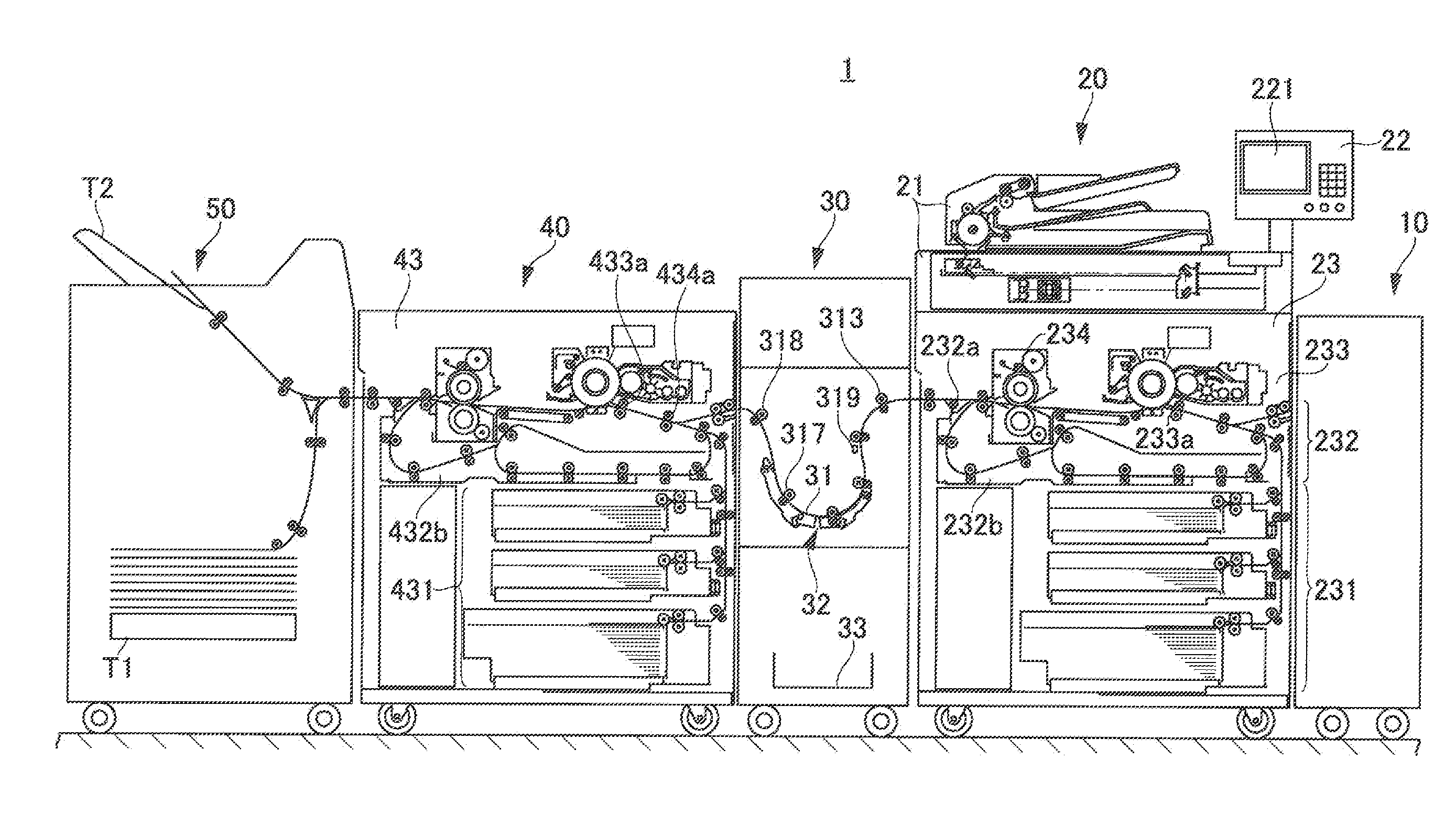
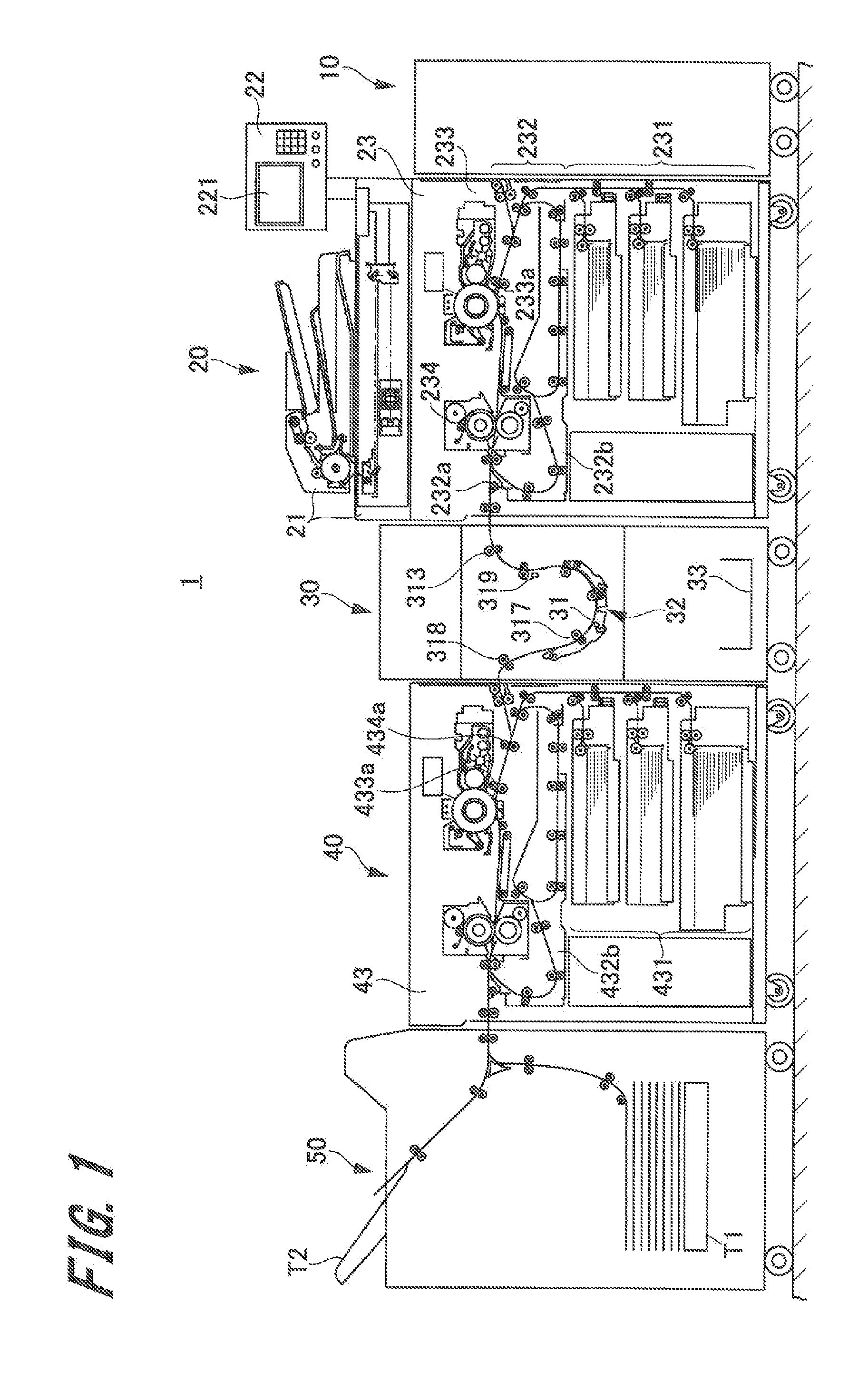
[0042]First, an outline of an image forming system according to a first embodiment of the present invention will be described by referring to FIG. 1. FIG. 1 is an outline view illustrating an entire configuration of the image forming system according to the first embodiment of the present invention.

[0043]As illustrated in FIG. 1, the image forming system 1 has a serial tandem configuration in which a paper feeding device 10, a first image forming apparatus 20, a sheet conveying device 30, a second image forming apparatus 40, a post-processing device 50 and the like are connected serially from an upstream side of a sheet conveying path.

[0044]The first image forming apparatus 20 and the second image forming apparatus 40 are set to be either of a main machine integrally managing the image forming system 1 and a sub machine operated in accordance with an instruction of the main machine when they are connected. In the embodiment, it is assumed...

second embodiment

2. Second Embodiment

Image Forming System

[0172]Subsequently, an image forming system according to a second embodiment of the present invention will be described. The image forming system of the embodiment is an example different from the first embodiment in the purge operation and the jamming processing at occurrence of jamming. The other configurations are similar to those in the first embodiment, and duplicated explanation will be omitted.

[0173]FIG. 14 is a flowchart at occurrence of jamming in the embodiment. Since Steps S11 to S13, S18, and S17 in FIG. 14 are the same as Step S1 to S4, S5 and S6 described in FIG. 12, the explanation will be omitted and the explanation will be made from Step S14.

[0174]If it is determined that the purge target sheet is in the sheet conveying device 30 or in the devices on the upstream side thereof (YES at Step S13), then, the control portion 360 determines whether or not a basis weight (g / m2) of the purge target sheet is at a reference value or mor...

third embodiment

3. Third Embodiment

Image Forming Apparatus

[0182]FIG. 15 is an outline view illustrating an entire configuration of an image forming system 100 according to a third embodiment of the present invention. In FIG. 15, the same reference numerals are given to the portions corresponding to those in FIG. 1, and duplicated explanation will be omitted.

[0183]In the image forming system 100 illustrated in FIG. 15, an intermediate device 60 is arranged between the first image forming apparatus 20 and the sheet conveying device 30. That is, the intermediate device 60 is arranged on the downstream side of the first image forming apparatus 20 and on the upstream side of the sheet conveying device 30 in the sheet conveying direction. In the embodiment, the intermediate device 60 conveys the sheet conveyed from the first image forming apparatus 20 to the sheet conveying device 30 in accordance with the instruction from the first image forming apparatus 20.

[0184]The intermediate device 60 includes an ...


PUM


Abstract

At occurrence of jamming, a downstream-side conveying roller pair is stopped, while an upstream-side conveying roller pair continuously rotates, whereby a sheet between the downstream-side conveying roller pair and the upstream-side conveying roller pair is ejected from a sheet conveying path opened by a movable guide portion. At this time, a conveying force of a stepping motor driving the upstream-side conveying roller pair is made larger than the conveying force before the occurrence of jamming.

Description

CROSS REFERENCES TO RELATED APPLICATIONS[0001]The present invention contains subject matter related to Japanese Patent Application JP 2014-021035, filed in the Japanese Patent Office on Feb. 6, 2014, the entire content of which being incorporated herein by reference.BACKGROUND OF THE INVENTION[0002]1. Field of the Invention[0003]The present invention relates to a tandem image forming system in which a plurality of image forming apparatuses are serially connected, a sheet conveying device arranged between the image forming apparatuses, and a control method of the sheet conveying device.[0004]2. Description of the Related Art[0005]A tandem image forming system constituted by serially connecting two image forming apparatuses (hereinafter referred to simply as an “image forming system”) is known. According to the image forming system, when an image is to be formed on both surfaces of a sheet, an image is formed on the front surface of the sheet by the upstream image forming apparatus, a...

Claims


Application Information

Patent Timeline
Patent Type & Authority Applications(United States)
IPC IPC(8): B65H7/06B65H5/26B65H7/20B65H5/06B65H7/12
CPCB65H7/06B65H5/068B65H5/26B65H7/20B65H7/12B65H5/062B65H5/36B65H2511/528B65H2513/10B65H2513/42B65H2513/51B65H2601/11G03G15/70G03G2215/00552
Inventor KANEKO, MASAHIRO
Owner KONICA MINOLTA INC
Why Eureka
Try Eureka