Rigid speed reducer with internal and external tooth profile tooth-enveloping

a technology of internal and external teeth and speed reducers, which is applied in the direction of toothed gearings, belts/chains/gearrings, and toothed gearings, can solve the problems of short service life of ensuring precision, affecting the accuracy of robot motion, and affecting the further improvement of load-bearing capacity of speed reducers, so as to improve the load-bearing capacity and transmission efficiency of speed reducers, the effect of large speed ratio

Active Publication Date: 2015-08-06
ZHEJIANG HENGFENGTAI REDUCER MFG
View PDF3 Cites 15 Cited by
  • Summary
  • Abstract
  • Description
  • Claims
  • Application Information

AI Technical Summary

Benefits of technology

[0015]Compared with the prior art, the invention has the following beneficial effects. According to the invention, large speed ratio speed-reduction motion is realized through meshing the tooth profiles of the internally and externally meshing curved gears, between which there is a small tooth difference, with the same fixed gear pins; since the same group of gear pins are shared in two-level reduction, the axial dimension of the speed reducer is reduced greatly compared with the dimension of the traditional simple series connection of two one-level speed reducers; and since one of force directions of the externally meshing curved gear and the internally meshing curved gear is outward in normal directions for which the gear pin is meshed with and tangent to the curved gears and the other one of the force directions is inward in the normal directions, it can be realized that meshing force for the internally and externally meshing curved gears is offset partially, which improves the load-bearing capacity and transmission efficiency of the speed reducer, eliminates that two eccentric gears of the RV speed reducer have to be disposed eccentrically at the difference of 180 degree, and thus also eliminates a requirement that two eccentric shaft sections are disposed on the eccentric shaft at a difference of 180 degree. According to the invention, only one eccentric gear arranged on the eccentric shaft is used for each level of speed-reduction of the speed reducer, and only two separate single eccentric gears are used for two-level reduction to enable realizing that the speed reducer is subjected to even force, thus structurally reducing, compared with the RV speed reducer, one cycloid gear and also one eccentric shaft section that has higher machining precision and has to meet bias of 180 degree, which not only reduces the axial dimension and loses the weight of the speed reducer, but also simplifies greatly the machining process and fabricating cost of the eccentric shaft and is easy to realize industrialization. In addition, the RV speed reducer uses composite two-level speed-reduction formed of planetary speed-reduction transmission and small-tooth-difference cycloidal pin gear speed-reduction, and compared with the two-level reduction having two small-tooth-differences, as for the same speed-reduction ratio, the number of teeth of the speed reducer according to the invention is far less than that of the RV speed reducer. For example, a planetary speed-reducing part of a RV40EQ speed reducer includes gears which respectively have 16 and 32 teeth, a cycloidal pin gear speed-reducing part of the RV40EQ speed reducer includes a cycloidal gear having 39 teeth and a pin gear having 40 teeth, and the total speed-reduction ratio is 81; and similarly to a transmission ratio of 80, for use in the invention, the internally meshing curved gear and the externally meshing curved gear respectively have 8 and 10 teeth, the pin gear has 9 teeth, and a total of 18 teeth of the curved gears and 9 teeth of the pin gear is used for the two-level speed-reduction, however 39 teeth of a pin gear and 87 teeth are to be used for RV two-level speed-reduction. As for the same size of speed reducer, the gear pins and the curved gears according to the invention can be made fat and thick, and can have strong rigidity. Particularly, the rigidity of the whole mechanism according to the invention is further improved after the enforcing frames are arranged additionally, that is, as for the same transmission ratio, the invention not only has high rigidity, a less tooth number, high load-bearing, and high efficiency, but also simplifies greatly the machining process and difficulty of the eccentric shaft, reduces the fabricating cost, is easy to realize industrialization, and is particularly applicable as a speed reducer for use in a heavy load robot, which has practical requirements of high rigidity, a small size, high load-bearing, high efficiency, and long service life for the speed reducer.

Problems solved by technology

The harmonic speed reducer, which was used as a main device for transmission of a robot, realizes speed-reduction motion through elastic deformation of a flexible gear, which has larger elastic deformation and also has a large elastic return difference caused thereby, thus inevitably affecting the accuracy of motion of the robot.
In the case of transmitting a larger load, meshing of a deformative flexible gear and a rigid gear is not conjugate tooth profile meshing, thus the service life for ensuring the precision is short, and the meshing of the deformative flexible gear and the rigid gear can only be applied on a light-load robot or middle-light-load robot instead of a heavy-load robot.
However, in the case that the size of the speed reducer is constant, a transmission ratio of the RV speed reducer increases as the number of teeth of a pin gear, and dimensions of a cycloidal single tooth and a gear pin become small, which affects the further improvement of load-bearing capacity of the speed reducer.
Moreover, the RV speed reducer is high in machining precision requirement and cost, which restricts popularization and application of the RV speed reducer.
Particularly, it is very difficult to meet machining precision with which two eccentric shafts are disposed at a difference of 180 degree, however the precision of the RV speed reducer directly affects transmission precision and efficiency of the speed reducer.

Method used


Image

  • Rigid speed reducer with internal and external tooth profile tooth-enveloping
  • Rigid speed reducer with internal and external tooth profile tooth-enveloping
  • Rigid speed reducer with internal and external tooth profile tooth-enveloping

Examples


Embodiment Construction

[0020]The invention is further explained below in conjunction with the drawings and embodiments.

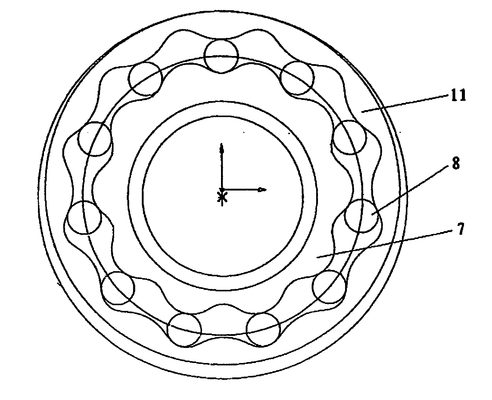
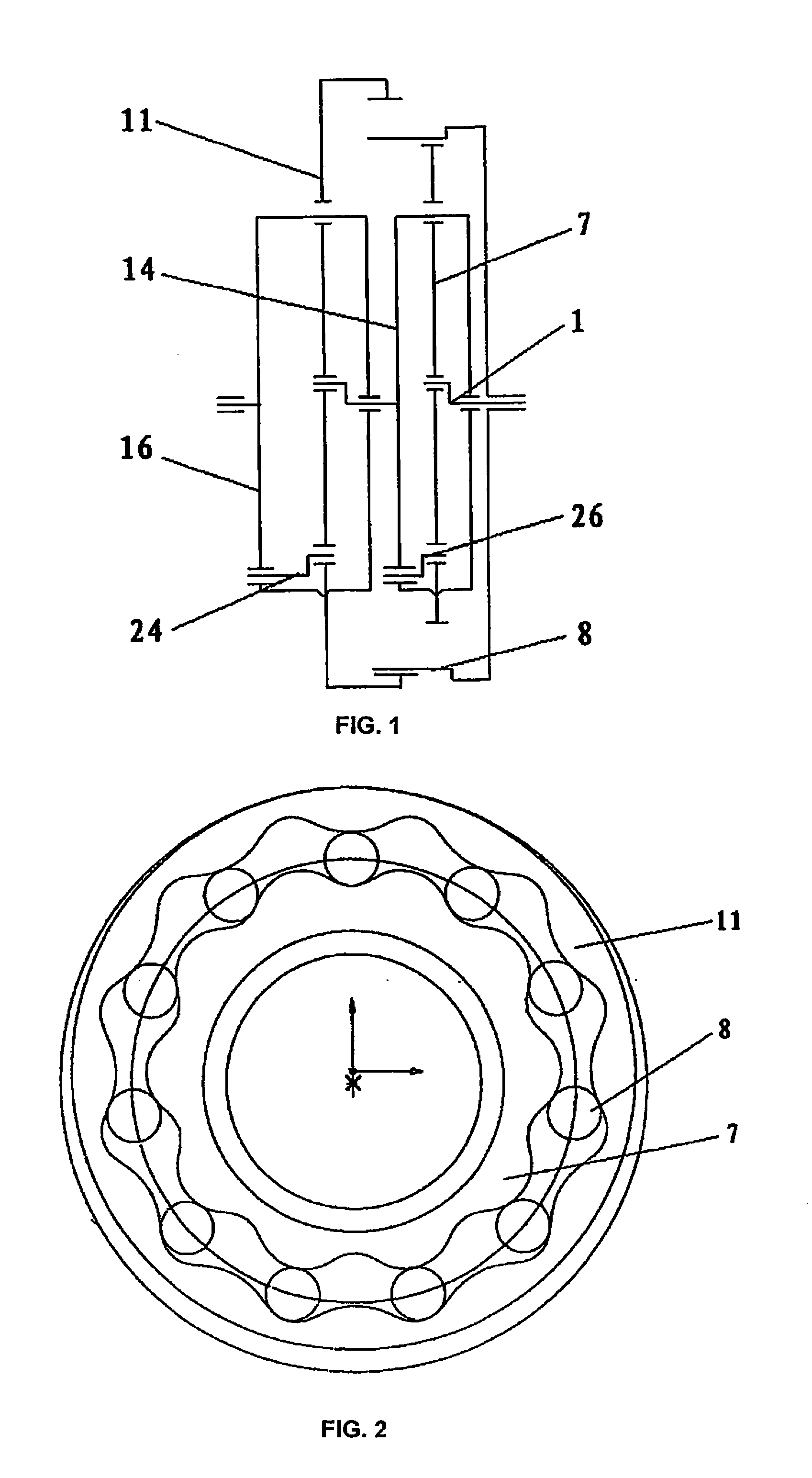
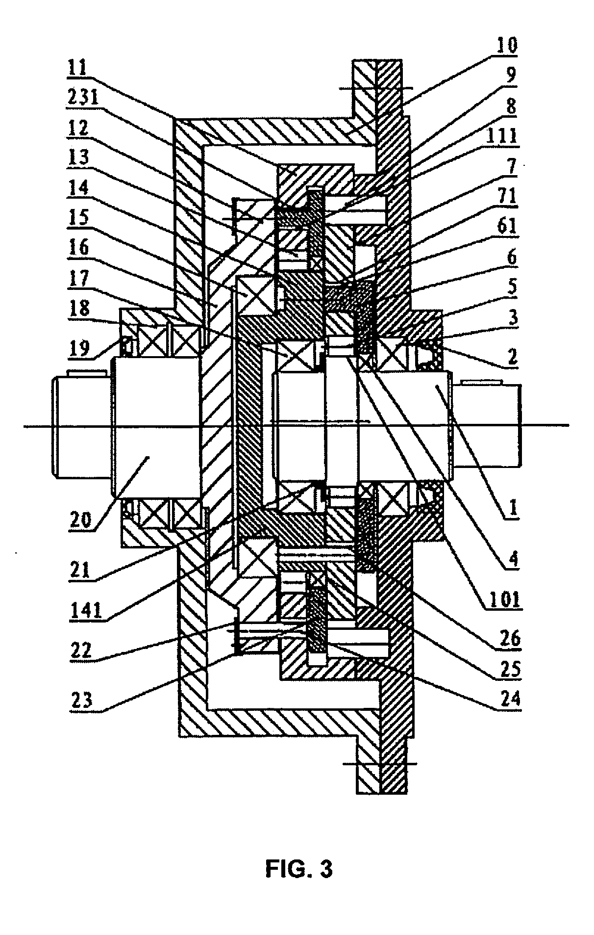
[0021]As shown in FIGS. 1 to 4, embodiments of a rigid speed reducer with internal and external tooth profile tooth-enveloping according to the invention include a first supporting frame 9 and a second supporting frame 10, which form an accommodating cavity; an input shaft 1 having an eccentric gear is arranged on the first supporting frame, and is mounted on the first supporting frame 9 through a first supporting bearing 3; an output shaft 20 is arranged on the second supporting frame 10, a part on the output shaft 20 which is located in the accommodating cavity is a output disk 16, the output shaft 20 is mounted on the second supporting frame 10 through a fourth supporting bearing 18; a first-level speed-reducing mechanism and a second-level speed-reducing mechanism are arranged in the accommodating cavity, wherein, the first-level speed-reducing mechanism includes an eccentric gear 101...


PUM


Abstract

A rigid speed reducer with internal and external tooth profile tooth-enveloping. The rigid speed reducer includes first- and second-level speed-reducing mechanisms. The first-level speed-reducing mechanism includes: an eccentric gear; rotary arm bearing; externally-meshing curved gear; and gear pins fixed on a first supporting frame and externally meshed with the externally-meshing curved gear. The second-level speed-reducing mechanism includes: an eccentric transmission gear; rotary arm bearing; internally-meshing curved gear, which is internally meshed and fitted with the gear pin; and an output disk linked with an output shaft. The eccentric transmission gear is in transmission connection with the externally-meshing curved gear through a dowel pin. The internally-meshing curved gear is in transmission with the output disk through a transmission pin. A first reinforcing frame is arranged at one side of the externally-meshing curved gear, and a second reinforcing frame is arranged at one side of the internally-meshing curved gear.

Description

RELATED APPLICATIONS[0001]The present application is a National Phase entry of PCT Application No. PCT / CN2013 / 0720955, filed Mar. 2, 2013, the disclosure of which is hereby incorporated by reference herein in its entirety.FIELD OF THE INVENTION[0002]The invention relates to a small-tooth-difference speed reducer for industrial use, and belongs to the technical field of a speed reducer. The invention is subsidized by “National High-tech R&D Program (863 Program)”.BACKGROUND OF THE INVENTION[0003]Speed reducers for use in the field of a robot are mainly classified into two kinds: a harmonic speed reducer and a cycloidal pin gear speed reducer. The harmonic speed reducer, which was used as a main device for transmission of a robot, realizes speed-reduction motion through elastic deformation of a flexible gear, which has larger elastic deformation and also has a large elastic return difference caused thereby, thus inevitably affecting the accuracy of motion of the robot. In the case of ...

Claims


Application Information

Patent Timeline
Patent Type & Authority Applications(United States)
IPC IPC(8): F16H1/32
CPCF16H25/06F16H2001/327F16H1/32F16H2025/063F16H2001/325
Inventor KONG, XIANGDONGYE, SHENGKANG
Owner ZHEJIANG HENGFENGTAI REDUCER MFG
Why Eureka
Try Eureka