
Radial-adjusting permanent magnetism speed adjusting device

A technology of permanent magnet speed regulation and magnetic steel, which is applied in the direction of electromechanical devices, electromechanical transmission devices, electrical components, etc., can solve the problems of large equipment vibration, difficult installation, large axial size, etc., and achieve reduced bearing heating and reasonable structural design , the effect of small axial size

Inactive Publication Date: 2016-01-13
TIANJIN JIXUAN ENERY SAVING TECH CO LTD
View PDF7 Cites 1 Cited by
  • Summary
  • Abstract
  • Description
  • Claims
  • Application Information

AI Technical Summary

Problems solved by technology

[0002] A transmission is a device that can change the transmission ratio or speed of its output shaft and input shaft; the reducer plays a role in matching the speed and transmitting torque between the prime mover and the working machine or the actuator; the application of the transmission and the reducer in modern machinery is Extremely extensive, but the transmission and the reducer are basically separate mechanical devices, and there are few variable speed reduction devices that integrate the two
Due to the special structure of most equipment, permanent magnet speed regulation cannot be realized or it is difficult to realize
Therefore, it is difficult to achieve energy saving for a large number of mechanical equipment and general equipment (pumps, fans, etc.)
The permanent magnet speed control devices (disc type and cylinder type) on the market now adopt the method of axially adjusting the air gap. Excessive vibration, high heat generation of bearings and short service life

Method used


Image

  • Radial-adjusting permanent magnetism speed adjusting device
  • Radial-adjusting permanent magnetism speed adjusting device
  • Radial-adjusting permanent magnetism speed adjusting device

Examples


Embodiment Construction

[0027] It should be noted that the embodiments in the invention and the features in the embodiments can be combined with each other if there is no conflict.

[0028] The specific embodiments created by the present invention will be described in detail below with reference to the accompanying drawings.

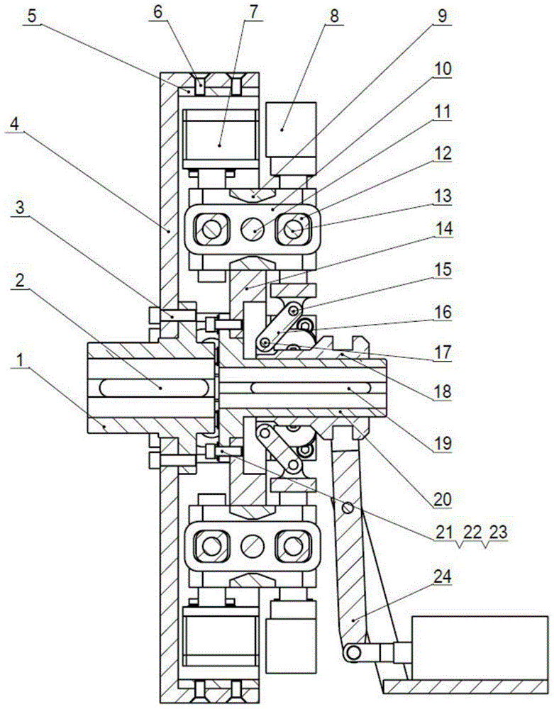
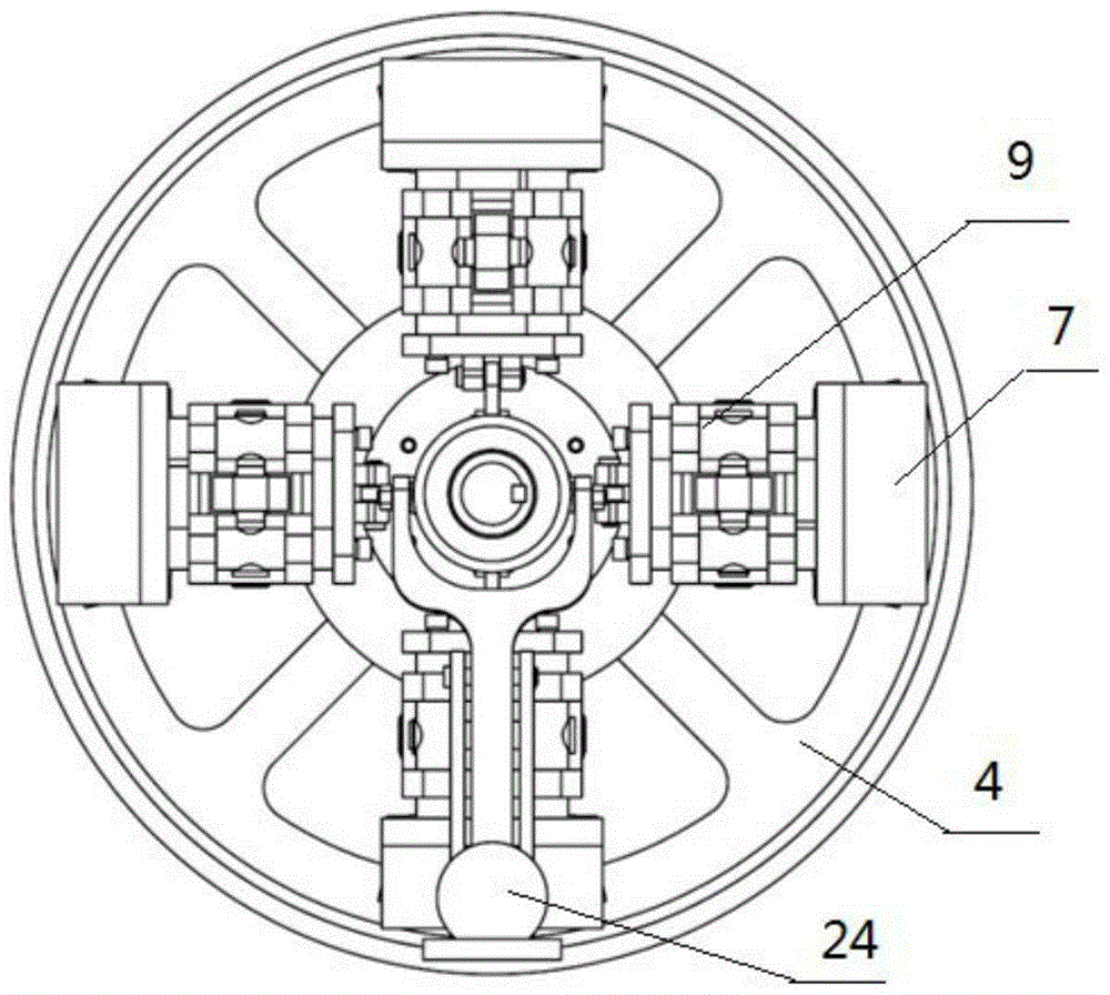
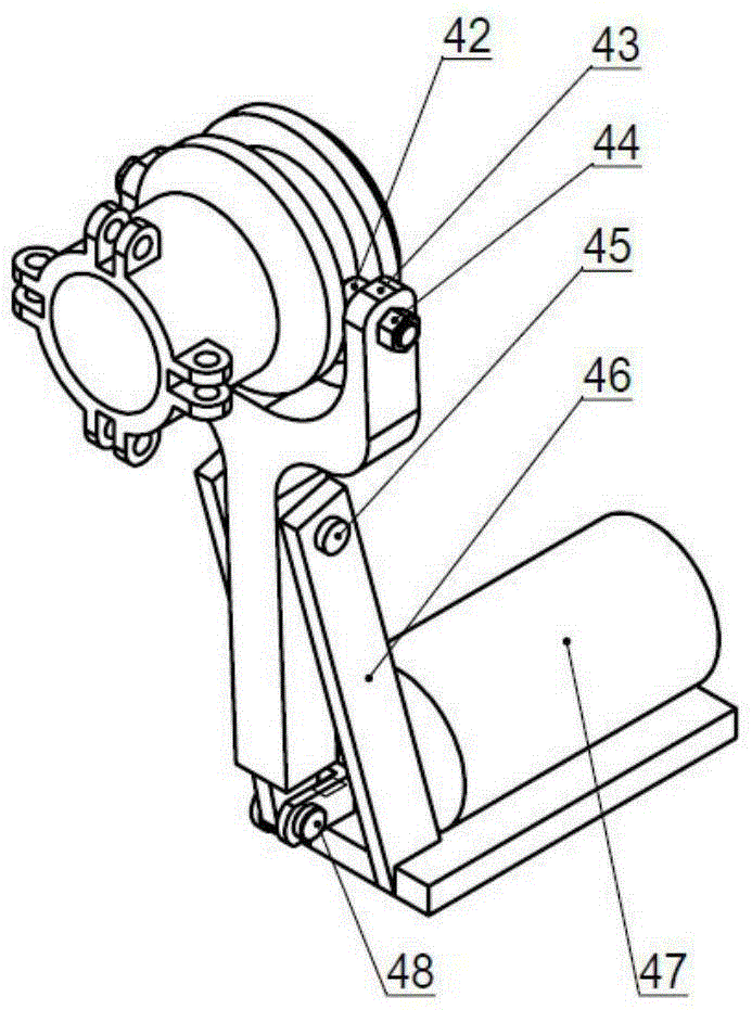
[0029] Such as Figure 1 to Figure 8 The shown a radially adjustable permanent magnet speed regulating device includes a first coupling 1 connected with a motor shaft and a second coupling 20 connected with a load shaft; the first coupling 1 is installed There is a conductor rotor 4 with a conductor ring 5 installed on the conductor rotor 4; a movable sleeve 18 is sleeved on the second coupling 20, and the movable sleeve 18 is driven by a driving mechanism 24 along the second coupling 20 The moving sleeve 18 is connected to a gap adjustment mechanism through a connecting rod 16; the gap adjustment mechanism is provided with a magnetic steel assembly 7 corresponding to the conductor...


PUM


Abstract

The invention provides a radial-adjusting permanent magnetism speed adjusting device, comprising a first shaft coupler in shaft connection with a motor and a second shaft coupler in connection with a load. A conductor rotor is mounted on the first shaft coupler. A conductor ring is mounted on the conductor rotor. A movable sleeve sleeves on the second shaft coupler, and is driven by a drive mechanism to slide along the axial direction of the second shaft coupler. The movable sleeve is connected with a gap adjusting mechanism via a connection rod. A magnetic steel assembly corresponding to the conductor ring is arranged on the gap adjusting mechanism. A magnetic-field air gap is left between the magnetic steel assembly and the conductor ring. According to the invention, radial adjustment of the air gap is adopted and the axial size is quite small, thereby saving space. In addition, the radial-adjusting permanent magnetism speed adjusting device is reasonable in structural design and there is no too great axial force on the motor and the load when the radial-adjusting permanent magnetism speed adjusting device is working, thereby prolonging the service lifetime of the load and a motor bearing and reducing the heat generated by the bearing. Furthermore, a magnetic line always goes along the shortest path, thereby achieving high efficiency.

Description

Technical field [0001] The invention belongs to the technical field of general reducer equipment, and particularly relates to a radially adjustable permanent magnet speed regulating device. Background technique [0002] The transmission is a device that can change the transmission ratio or speed of its output shaft and input shaft; the reducer plays the role of matching the speed and transmitting torque between the prime mover and the working machine or the actuator; the application of the transmission and the reducer in modern machinery It is extremely wide, but the transmission and the reducer are basically separate mechanical devices, and there are few speed reduction devices that integrate the two. Due to the special structure of most equipment, permanent magnet speed regulation cannot be realized or is difficult to realize. Therefore, a large number of mechanical equipment and general equipment (pumps, fans, etc.) are difficult to achieve energy saving. At present, the per...

Claims


Application Information

Patent Timeline
Patent Type & Authority Applications(China)
IPC IPC(8): H02K51/00
Inventor 柳志明张领强
Owner TIANJIN JIXUAN ENERY SAVING TECH CO LTD
Learn More