Actuating drive and method for cooling a solid body actuator housed in an actuating drive with an actuating element

a solid body actuator and drive technology, applied in the direction of magnetostrictive devices, device details, device details, etc., can solve the problems of solid body actuators losing geometric dimensional stability, actuating drives, and prone to heating, so as to avoid the loss of coolant

Inactive Publication Date: 2015-08-06
FRAUNHOFER GESELLSCHAFT ZUR FOERDERUNG DER ANGEWANDTEN FORSCHUNG EV
View PDF0 Cites 47 Cited by
  • Summary
  • Abstract
  • Description
  • Claims
  • Application Information

AI Technical Summary

Benefits of technology

[0017]Appropriate coolants may be selected from gas-phase and liquid substances depending on the structural design of the actuating drive, and also on the intended use and purpose thereof. In an advantageous variation of the cooling according to the invention for solid body actuators integrated in actuating drives, the cooling medium transported away from the solid body actuator, which itself undergoes warming as a result of thermal coupling due to the extraction of heat from the solid body actuator, undergoes a cooling process that is external, that is spatially separate from actuating drive, and after corresponding cooling is returned to the solid body actuator in a closed circuit. In this way, loss of coolant is avoided.

Problems solved by technology

Actuating drives in which solid body actuators—preferably based on piezoelectric or magnetostrictive materials which are integrated for the purpose of travel deflection, are prone to heating particularly during dynamic power operation due to the hysteresis inherent in the transducer material and the enclosure of the solid body actuator required by the system.
If no measures are implement to cool the solid body actuator, not only is there a danger that the solid body actuator may lose geometric dimensional stability due to thermal expansion of the material, but if the material-specific Curie temperature is exceeded, the energy transducing properties acquired by the material are lost.
Moreover, operationally induced self-heating of the solid body actuator results mostly in an increased electrical power requirement, which has a very detrimental effect on the activation of the solid body actuator.

Method used


Image

  • Actuating drive and method for cooling a solid body actuator housed in an actuating drive with an actuating element
  • Actuating drive and method for cooling a solid body actuator housed in an actuating drive with an actuating element
  • Actuating drive and method for cooling a solid body actuator housed in an actuating drive with an actuating element

Examples


Embodiment Construction

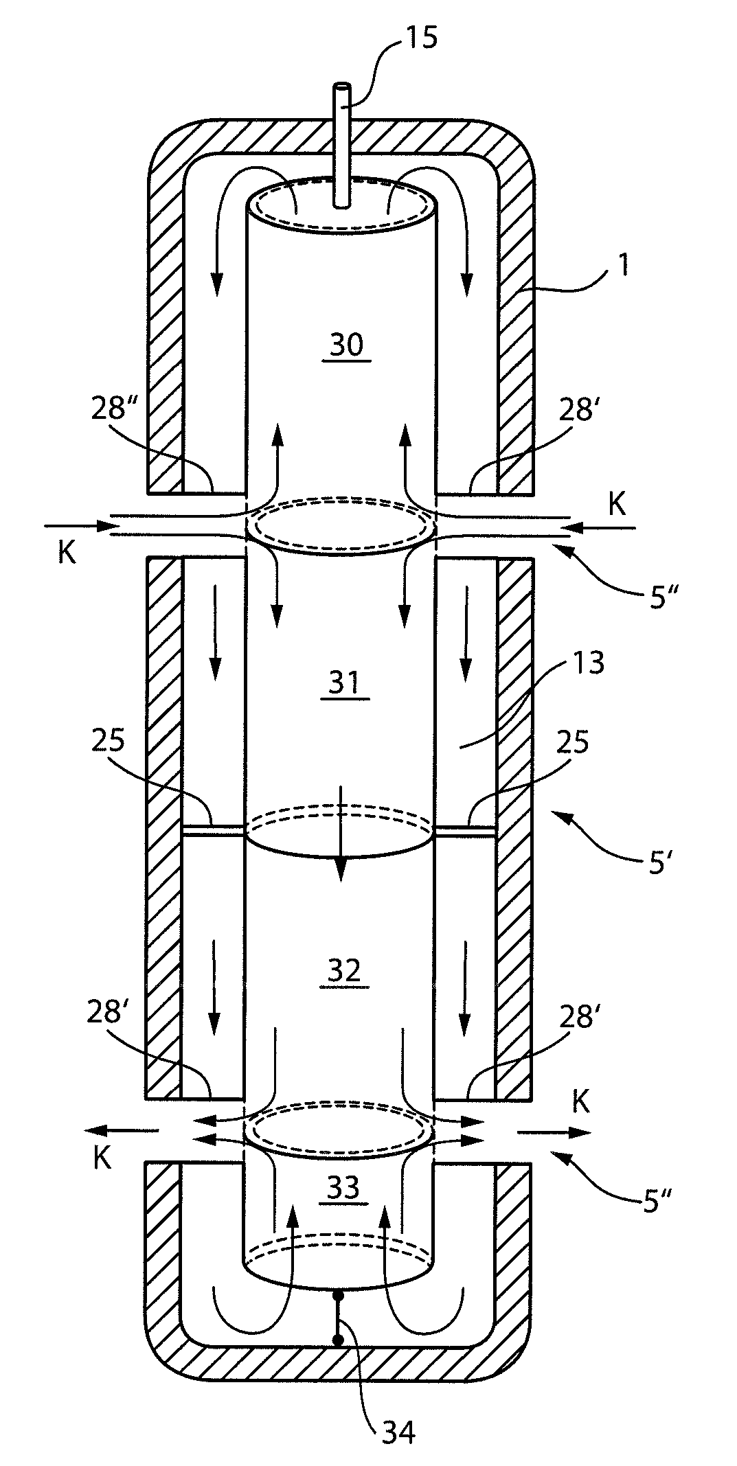
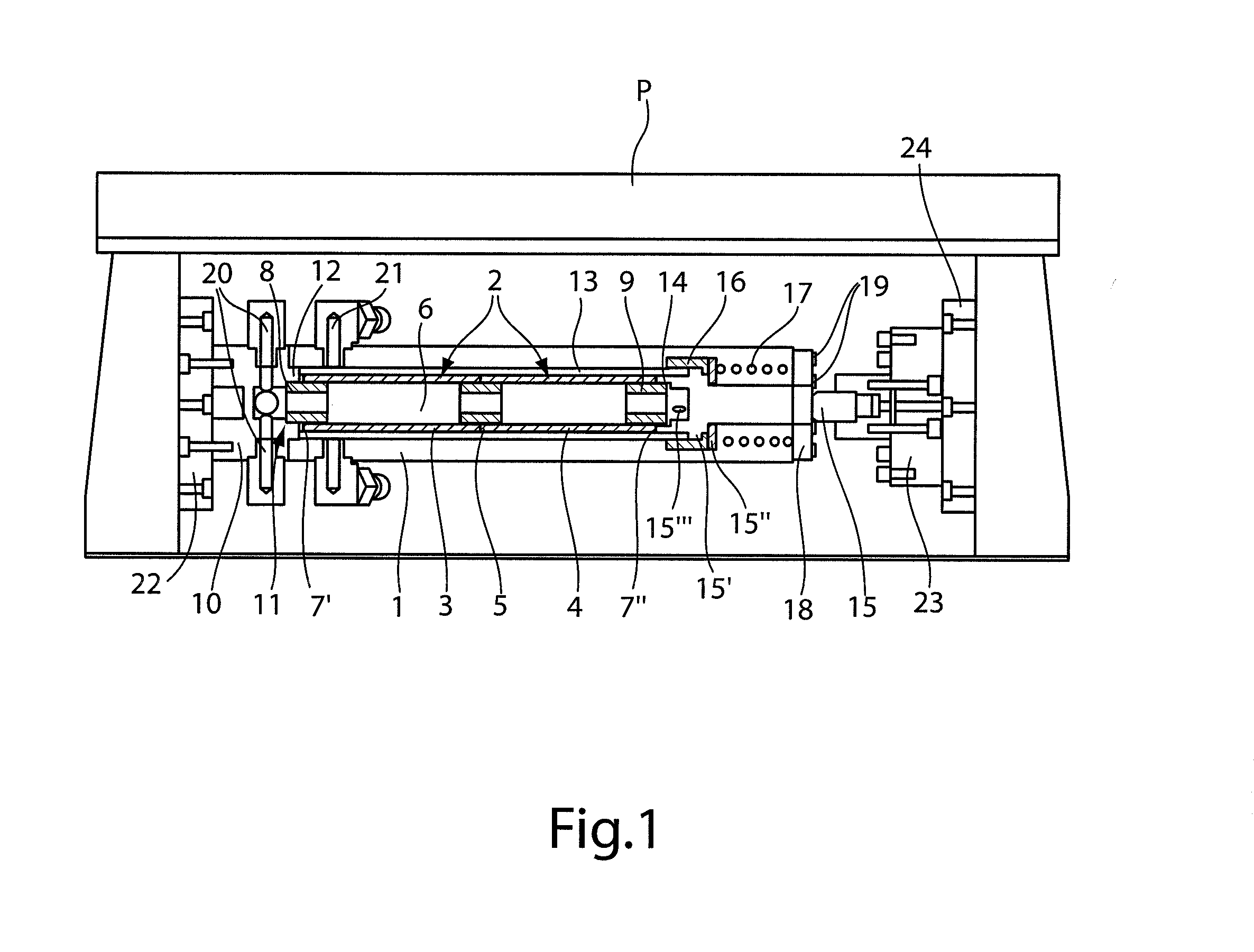
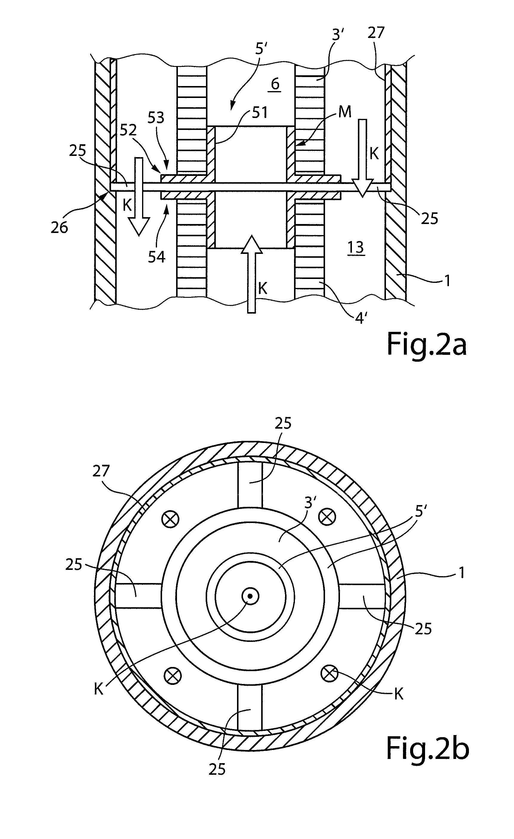
[0025]FIG. 1 shows a longitudinal section through an actuating drive configured according to the invention, which provides a solid body actuator 2 made from piezoelectric material inside a housing 1. The actuator is constructed in the embodiment shown from two hollow cylindrical piezoelectric solid body elements 3 and 4. The hollow cylindrical piezoelectric solid body elements 3 and 4 are joined by a connecting element 5, preferably made of plastic and in the form of a sleeve, to form a unitary hollow cylindrical body enclosing a hollow inner duct 6.

[0026]The individual piezoelectric solid body elements 3 and 4 are each shaped from a monolithic piezoelectric material into a hollow cylinder, and electrodes are attached to both hollow cylindrical end faces thereof, via which an electrical voltage is applied to cause a controlled longitudinal expansion of piezoelectric solid body elements 3 and 4. Alternatively, it is also possible to combine the individual, hollow cylindrical piezoele...


PUM


Abstract

The invention ris an actuating drive for deflecting an actuating element by a solid body actuator (2) which, when an electrical voltage or an alternating magnetic field is applied, experiences a length change. A housing (1) encloses the solid body actuator to define an interspace (13) in a fluid-tight manner. Furthermore, the solid body actuator includes a hollow duct (6) having one end connected to a first hollow conduit (20) passing through the housing and the other end opening into the interspace. The interspace is additionally connected in a fluid-tight manner to a second hollow conduit (21) passing through the housing.

Description

CROSS REFERENCE TO RELATED APPLICATIONS[0001]Reference is hereby made to German Patent Application No. DE10 2010014 892.5, filed on Jul. 27, 2013 and PCT / EP2013 / 002192, filed Jul. 23, 2014, which applications are incorporated herein by reference in their entirety.BACKGROUND OF THE INVENTION[0002]1. Field of the Invention[0003]The invention relates to an actuating drive for uniaxial, bi-directional deflection of an actuating element, which can be actuated directly or indirectly by a solid body actuator, which has at least one solid body actuator end braced on a frontal face in a housing that undergoes a change in length in a longitudinal extension that is assignable to the solid body actuator in response to a change in an electrical voltage that may be applied to the solid body actuator or a magnetic field acting on the solid body actuator, depending on the actuator type, and which may be transferred directly or indirectly to the actuating element via a second frontal face opposite t...

Claims


Application Information

Patent Timeline
Patent Type & Authority Applications(United States)
IPC IPC(8): H01L41/09H01L41/06H01L41/12H01L41/053
CPCH01L41/053H01L41/0835H01L41/0906H01L41/06H01L41/12H10N35/80H10N30/886H10N30/505H10N30/88H10N35/00H10N30/202
Inventor MELZ, TOBIASMATTHIAS, MICHAELHANSELKA, HOLGER
Owner FRAUNHOFER GESELLSCHAFT ZUR FOERDERUNG DER ANGEWANDTEN FORSCHUNG EV
Why Eureka
Try Eureka