
Spin-welded electrical ground and spin welding methods

a technology of electrical ground and spin welding, which is applied in the direction of connection contact material, coupling device connection, conductor, etc., can solve the problems of not being able to rely on the approaches developed in the past to prepare electrical ground for aluminum-based vehicles, and being used in arc welding processes that are sensitive and expensive to fabricate electrical grounds

Active Publication Date: 2015-08-06
FORD GLOBAL TECH LLC
View PDF13 Cites 9 Cited by
  • Summary
  • Abstract
  • Description
  • Claims
  • Application Information

AI Technical Summary

Benefits of technology

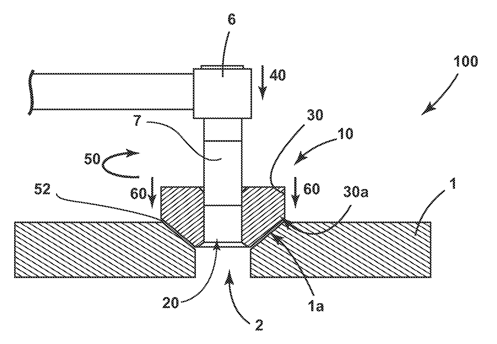
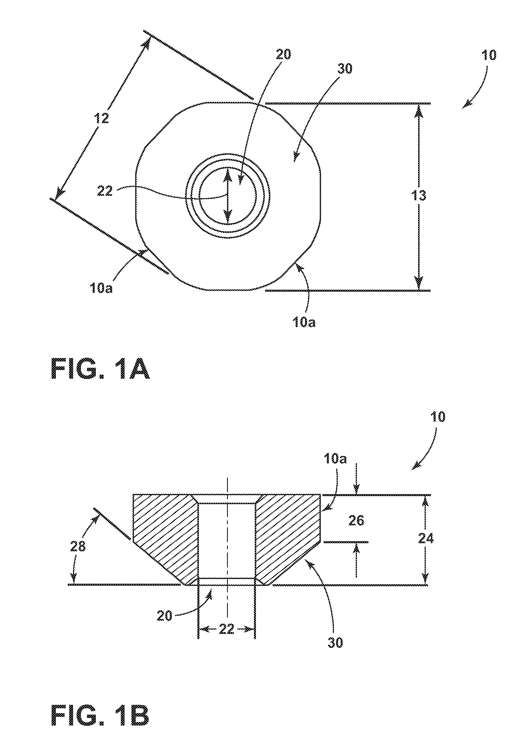
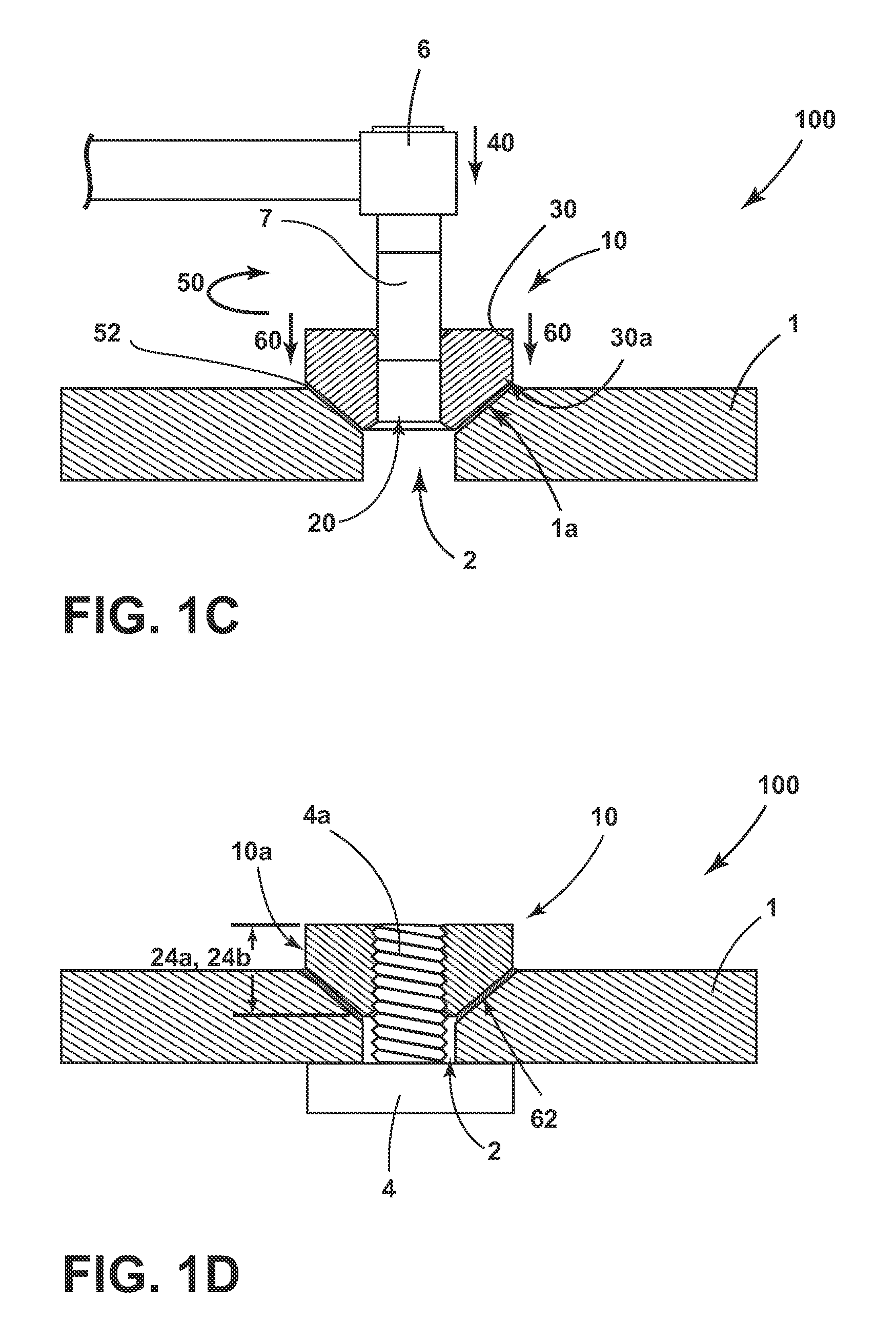
The present invention provides a method for making a ground by rotating an aluminum alloy weld nut and lowering its outer wall into contact with an alloy substrate to create a frictional force for a set amount of time. This friction is then stopped and an axial forging force is applied for a set amount of time to create the final ground. This method creates a strong and reliable ground that is resistant to wear and corrosion.

Problems solved by technology

Often, fairly expensive and sensitive arc welding processes are employed to fabricate these electrical grounds.
The approaches used to prepare electrical grounds for these aluminum-based vehicles cannot be based on those developed in the past for vehicles employing steel and / or other ferrous-based metal components.

Method used


Image

  • Spin-welded electrical ground and spin welding methods
  • Spin-welded electrical ground and spin welding methods
  • Spin-welded electrical ground and spin welding methods

Examples


Embodiment Construction

[0019]As required, detailed embodiments of the present invention are disclosed herein; however, it is to be understood that the disclosed embodiments are merely exemplary of the invention that may be embodied in various and alternative forms. The figures are not necessarily to a detailed design; some schematics may be exaggerated or minimized to show function overview. Therefore, specific structural and functional details disclosed herein are not to be interpreted as limiting, but merely as a representative basis for teaching one with ordinary skill in the art to variously employ the present invention.

[0020]For purposes of description herein, the terms “upper,”“lower,”“right,”“left,”“rear,”“front,”“vertical,”“horizontal,” and derivatives thereof shall relate to the components illustrated in FIG. 1C. However, it is to be understood that the invention may assume various alternative orientations, except where expressly specified to the contrary. It is also to be understood that the spe...


PUM

PropertyMeasurementUnit
inner diameteraaaaaaaaaa
distanceaaaaaaaaaa

Abstract

A friction-welded ground assembly that includes an alloy substrate with a clearance hole; an aluminum alloy weld nut having a bolt bore and an outer wall; and a grounding bolt. The bore is located substantially within the clearance hole and a portion of the outer wall is joined to the substrate at a friction-welded attachment. Further, the bolt is threaded within the bore. In addition, a method for making a ground includes the steps: rotating an aluminum alloy weld nut having an outer wall at a predetermined speed; lowering the outer wall of the rotating nut into contact with an aluminum alloy substrate to generate a frictional force for a friction time; arresting the rotation of the nut; and applying an axial forging force to the outer wall and the substrate for a forging time.

Description

FIELD OF THE INVENTION[0001]The present invention generally relates to friction-welded assemblies, particularly spin-welded, electrical ground assemblies for vehicular applications.BACKGROUND OF THE INVENTION[0002]Electrical ground assemblies are numerous in technology-oriented products that rely on electrical and / or electronic components, including vehicles. In automotive applications, electrical ground assemblies are often installed in sheet metal at various locations within the vehicle. Often, fairly expensive and sensitive arc welding processes are employed to fabricate these electrical grounds.[0003]More recently, large-scale production vehicles are evolving to incorporate more aluminum alloy components. Aluminum alloys offer corrosion resistance and weight savings compared to the steels employed in earlier generation vehicles, particularly for sheet metal components. The approaches used to prepare electrical grounds for these aluminum-based vehicles cannot be based on those de...

Claims


Application Information

Patent Timeline
Patent Type & Authority Applications(United States)
IPC IPC(8): H01R4/02H01R13/621
CPCH01R13/6215H01R4/029H01R4/64H01R2201/26B23K20/129B23K20/1295B23K20/227B23K20/2336B23K2101/38B23K2103/04B23K2103/10B23K2103/20B23K20/12H01R4/02H01R4/62H01R13/648
Inventor DUPUIS, LAWRENCE J.DANYO, MICHAEL WILLIAMLAZARZ, KIMBERLY ANNREWALT, STEVEN
Owner FORD GLOBAL TECH LLC
Learn More