
Tyre-changing machine

a technology of tyres and rims, which is applied in the field of tyre-changing machines, can solve the problems of tyre damage, bead breaking devices, perforation of tyres and/or rim damage, etc., and achieve the effect of reducing/eliminating the chance of damage to tyres and/or rims

Inactive Publication Date: 2015-08-13
SICAM SRL +1
View PDF8 Cites 2 Cited by
  • Summary
  • Abstract
  • Description
  • Claims
  • Application Information

AI Technical Summary

Benefits of technology

The present invention aims to provide a tyre-changing machine that can reduce or eliminate the chance of damaging the tyre and rim during the bead breaking procedure. It also aims to allow for the secure fitting of run-flat tyres that have been damaged and can be fitted multiple times. The invention provides a simple, effective, and affordable solution to overcome the drawbacks of prior art.

Problems solved by technology

As a consequence, an operator has more chances to damage a tyre during its removal so that tyre manufacturers advise against mounting a run-flat tyre again because of the damage occurred during the fitting and removal procedure.
There are several drawbacks for this first type of bead breaking device.
In particular, it is underlined that the tool applies on the bead a very intense force instantaneously and this may lead to the perforation of the tyre and / or the damage to the rim.
To this it is added that, inconveniently, the bead breaking procedure must be repeated twice, one for each bead.
These concentrated and localized forces, in combination with the rotation of the tyre and the rim, increase the chances of damaging the tyre.
The application of a force on the tyre flank and the simultaneous rotation of the wheel, in fact, may lead to the formation of cuts inside the tyre which the operator, during the job, may not be aware of and which can cause the ultimate breakage of the tyre at a later time, e.g. when the wheel has already been remounted on the vehicle and the possible damage can also be more serious.
This problem is particularly felt for run-flat tyres.
Furthermore, in the traditional bead breaking devices there isn't any control of the force applied by the arms, which are controlled individually and do not allow both beads to be detached simultaneously.
The bead breaking procedure is therefore very long.

Method used


Image

  • Tyre-changing machine
  • Tyre-changing machine
  • Tyre-changing machine

Examples


Embodiment Construction

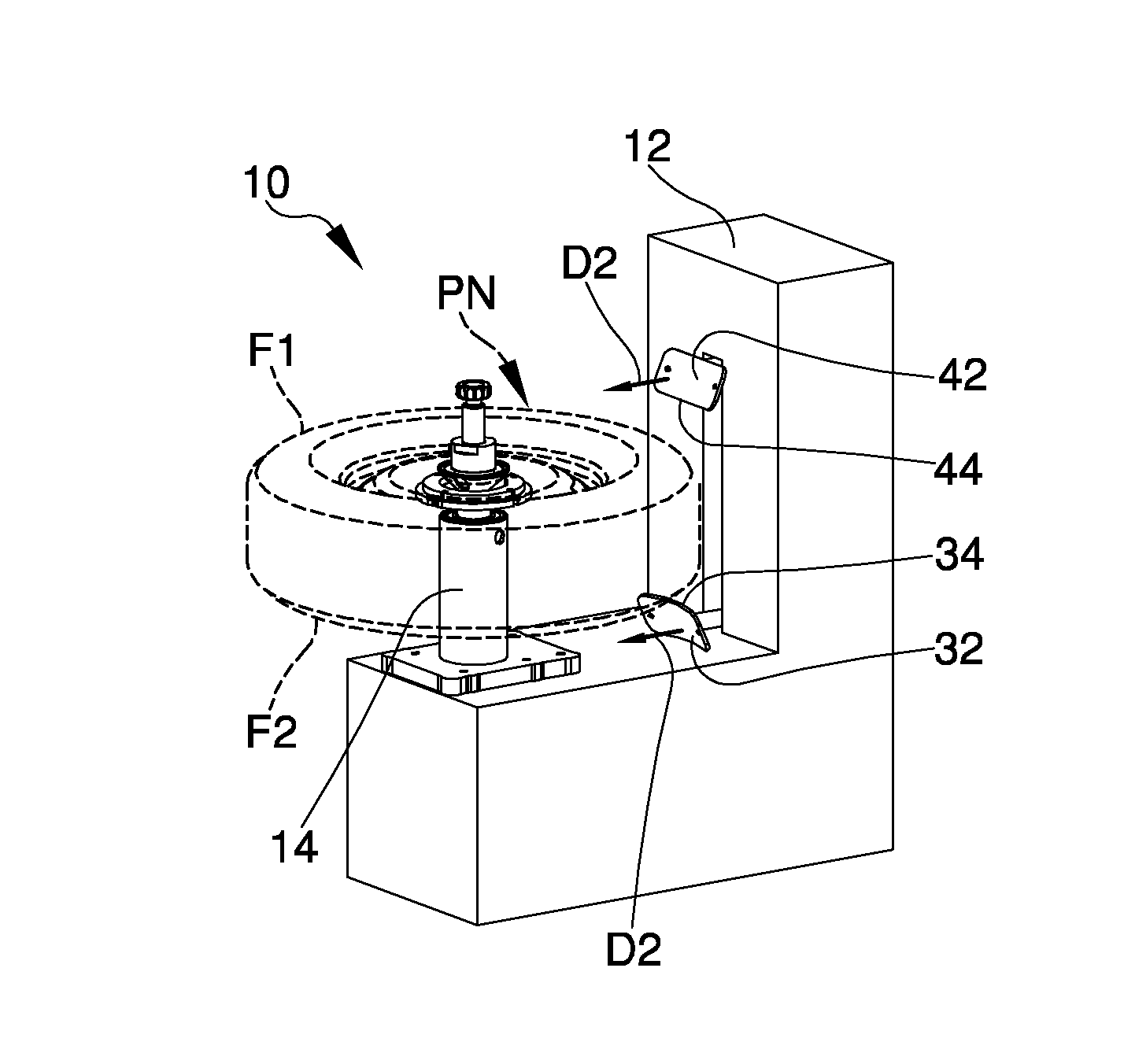
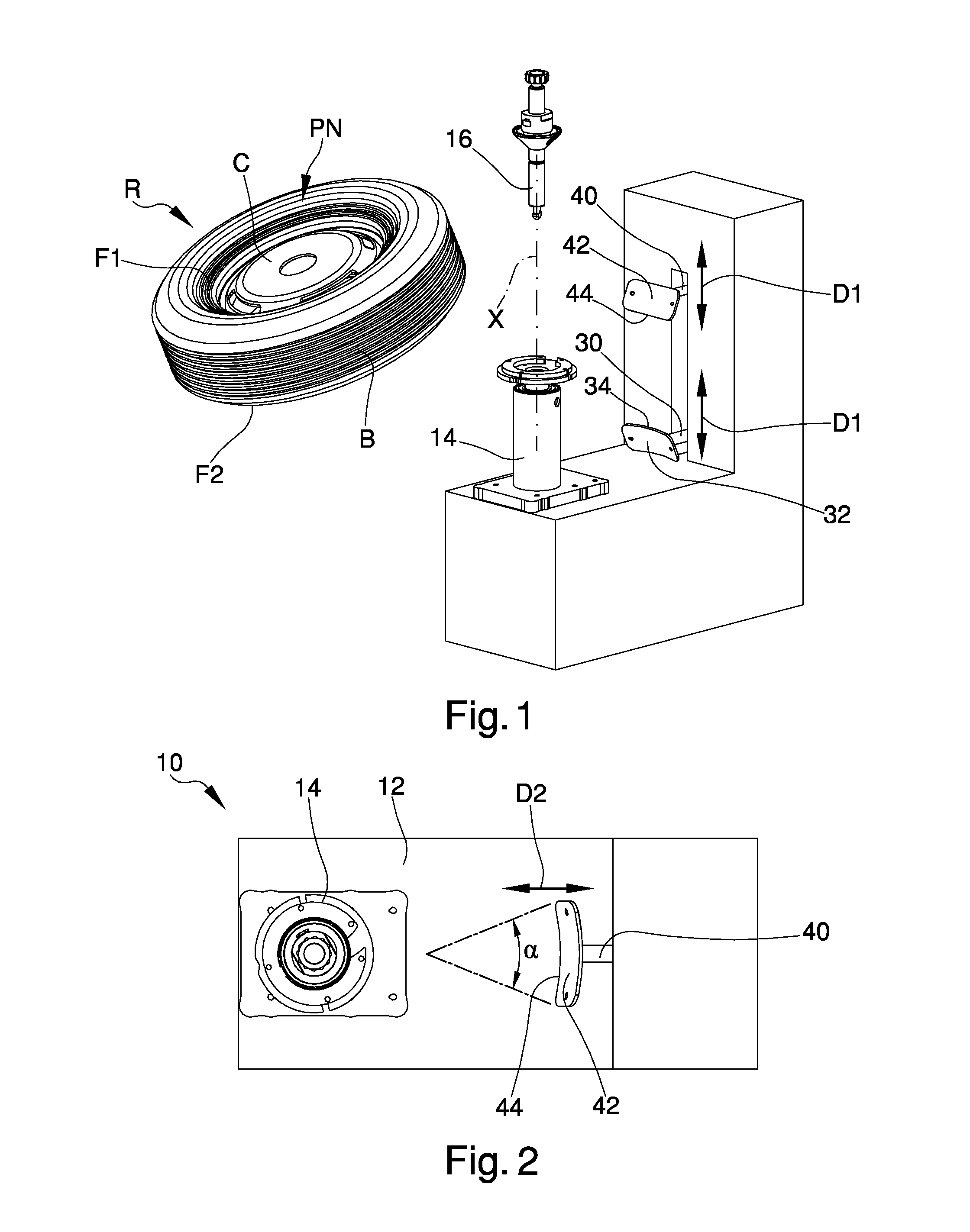
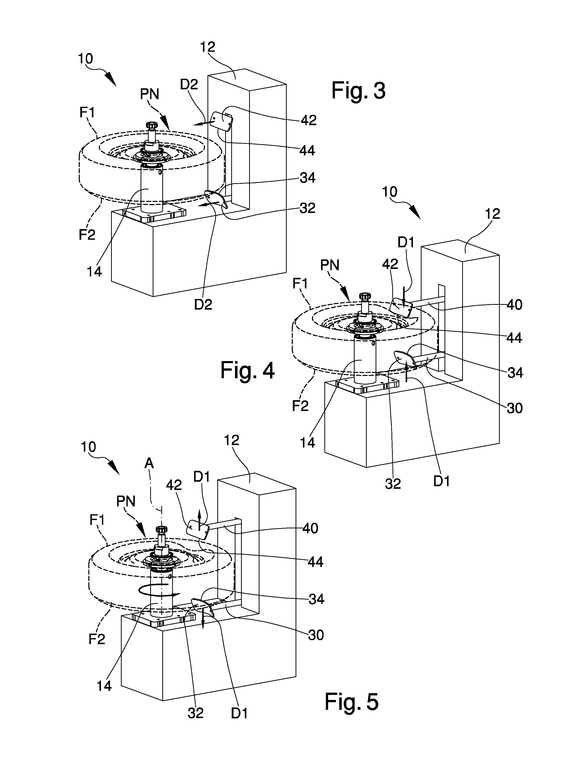
[0039]With particular reference to such illustrations, globally indicated with reference number 10 is a tyre-changing machine for a wheel R.

[0040]The wheel R comprises in a known manner a rim C on which is mounted a tyre PN having a portion of tread B and two opposite flanks, of which a first flank F1 and a second flank F2.

[0041]The machine 10 comprises a base or bed 12 for resting on the ground, from which extends a spindle 14 on which the wheel R is mountable.

[0042]The spindle 14 is configured to tighten the rim C on the bed 12, e.g. by means of a locking clamp or hub 16 which can be interlocked or screwed into the spindle 14.

[0043]The rim C is tightened so as to place the wheel R with the first flank F1 arranged in a distal position with respect to the bed 12 and the second flank F2 arranged in a proximal position with respect to the bed 12.

[0044]In other words, when the wheel R is fitted on the spindle 14, the first flank F1 is located farther from the bed 12 with respect to the...


PUM


Abstract

The tyre-changing machine (10) for fitting and removing vehicle wheels includes:a bed (12) for resting on the ground;a spindle (14) which extends from the bed (12) and on which is mountable a wheel (R) having a rim (C) and a tyre (PN) with two opposite flanks (F1, F2), the spindle (14) being configured to tighten the rim (C) on it and able to put in rotation the wheel (R) around an axis of rotation (A); andtwo bead breaking tools (32, 42) which are movable one towards the other in the proximity of the spindle (14) along a bead-breaking direction (Di) substantially parallel to the axis of rotation (A) of the spindle (14), the bead breaking tools (32, 42) having respective non-rolling contact surfaces (34, 44) able to contact and push in use the opposite flanks with the wheel (R) mounted on the spindle.

Description

FIELD OF THE INVENTION[0001]The present invention relates to a tyre-changing machine for fitting and removing wheels of vehicles.BACKGROUND OF THE INVENTION[0002]The wheels for vehicles consist of a metal rim having, at its axial extremities, annular containment flanges between which a groove is defined for inserting a tyre by interlocking[0003]In the mounting configuration, the lateral portions of the tyre, so-called “beads”, abut against the containment flanges.[0004]An air chamber can be inserted in the tyre or, in case of “tubeless” tyres, pressurized air can be introduced directly.[0005]Tyre-changing machines are currently employed to perform the fitting and removal operations of tyres onto and from the relative rims.[0006]They allow to remove the tyre from its rim, for example to perform maintenance or replacement jobs on the air chamber, the rim and / or the tyre itself, and then to mount it again, or place a new one, on the rim.[0007]The tyre-changing machines generally have a...

Claims


Application Information

Patent Timeline
IPC IPC(8): B60C25/13B60C25/05
CPCB60C25/0527B60C25/13B60C25/138B60C25/0536B60C25/125
Inventor IMMLER, MICHAELEGLE, KARLMACCHIA, ADRIANOVESCOVINI, MARCO
Owner SICAM SRL
Learn More