Tilt Wing Aerial Vehicle

a technology of tilting wing and aerial vehicle, which is applied in the field of tilting wing aerial vehicle, can solve the problems of increasing complexity, complexity and weight of payload, increasing complexity and weight, and increasing complexity and weight. the effect of wing segment translation

Active Publication Date: 2015-08-13
NORTHROP GRUMMAN SYST CORP
View PDF15 Cites 48 Cited by
  • Summary
  • Abstract
  • Description
  • Claims
  • Application Information

AI Technical Summary

Benefits of technology

[0014]In the presently preferred embodiment the first segment of the first wing and the first segment of the second wing are attached to a collar formed in the fuselage. The...

Problems solved by technology

The particular manner in which an aircraft translates from horizontal to vertical mode is significant, as complex systems may be more expensive and subject to greater operational failure.
While mechanical scanning systems and electronic scanning systems, ...

Method used


Image

  • Tilt Wing Aerial Vehicle
  • Tilt Wing Aerial Vehicle
  • Tilt Wing Aerial Vehicle

Examples


Embodiment Construction

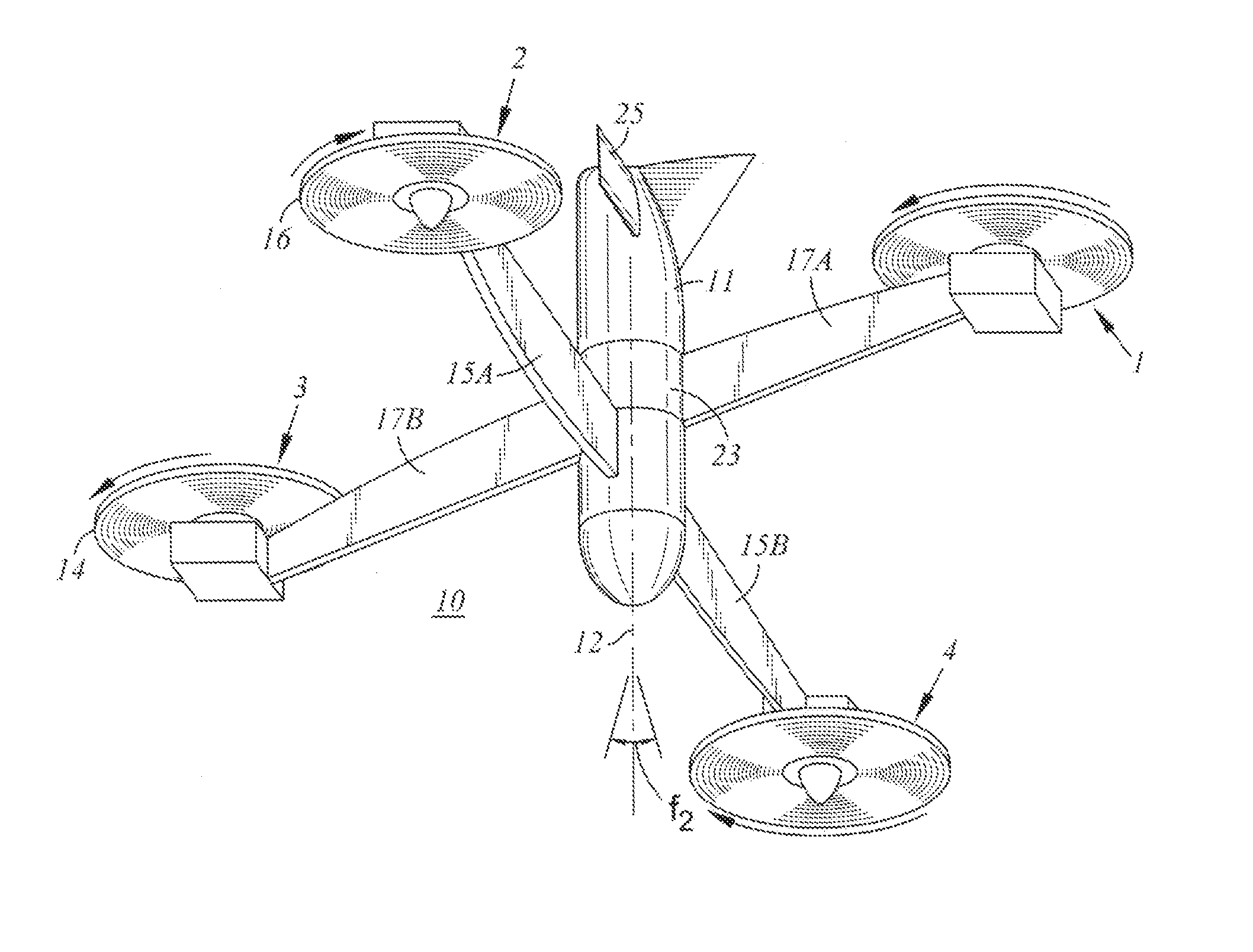
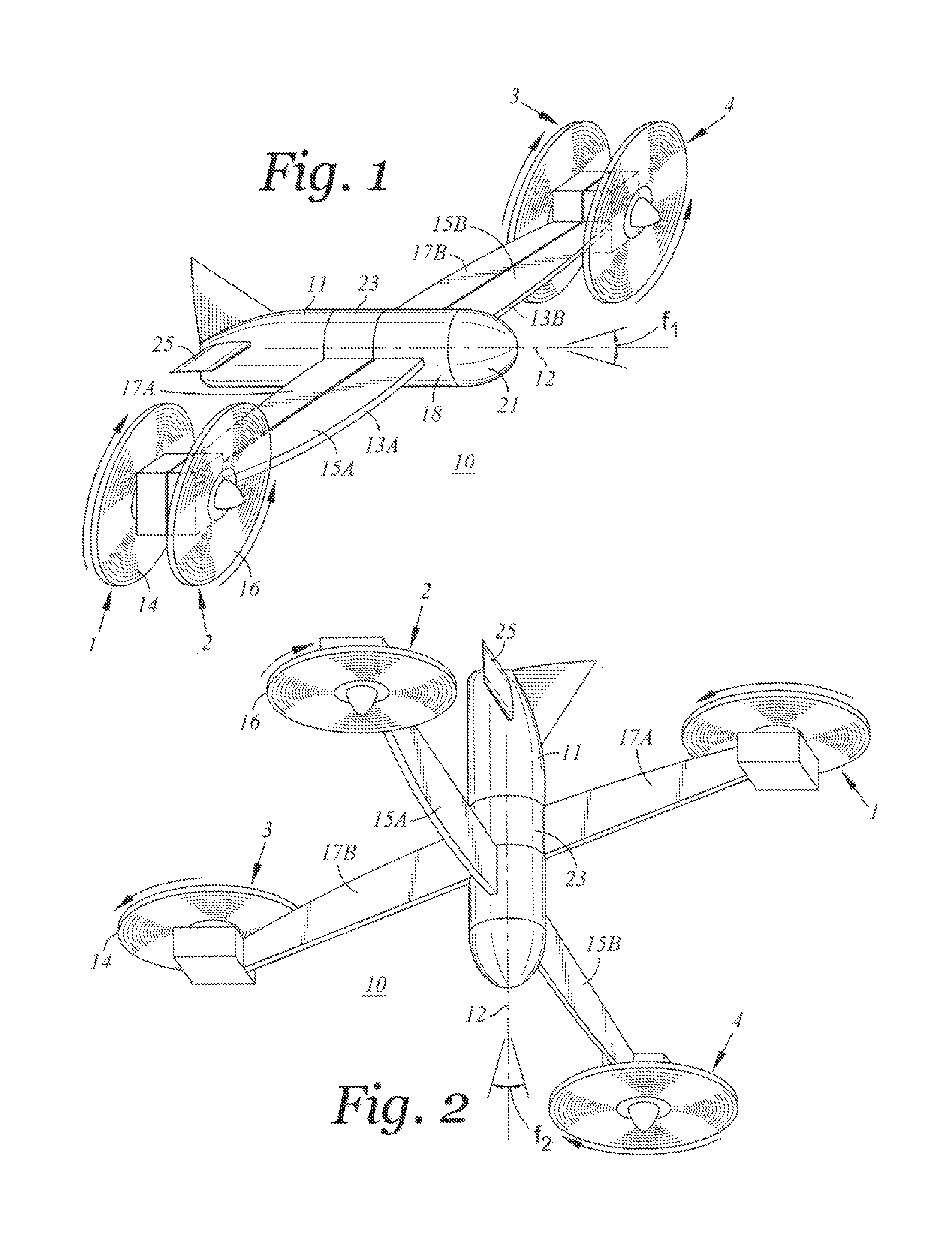
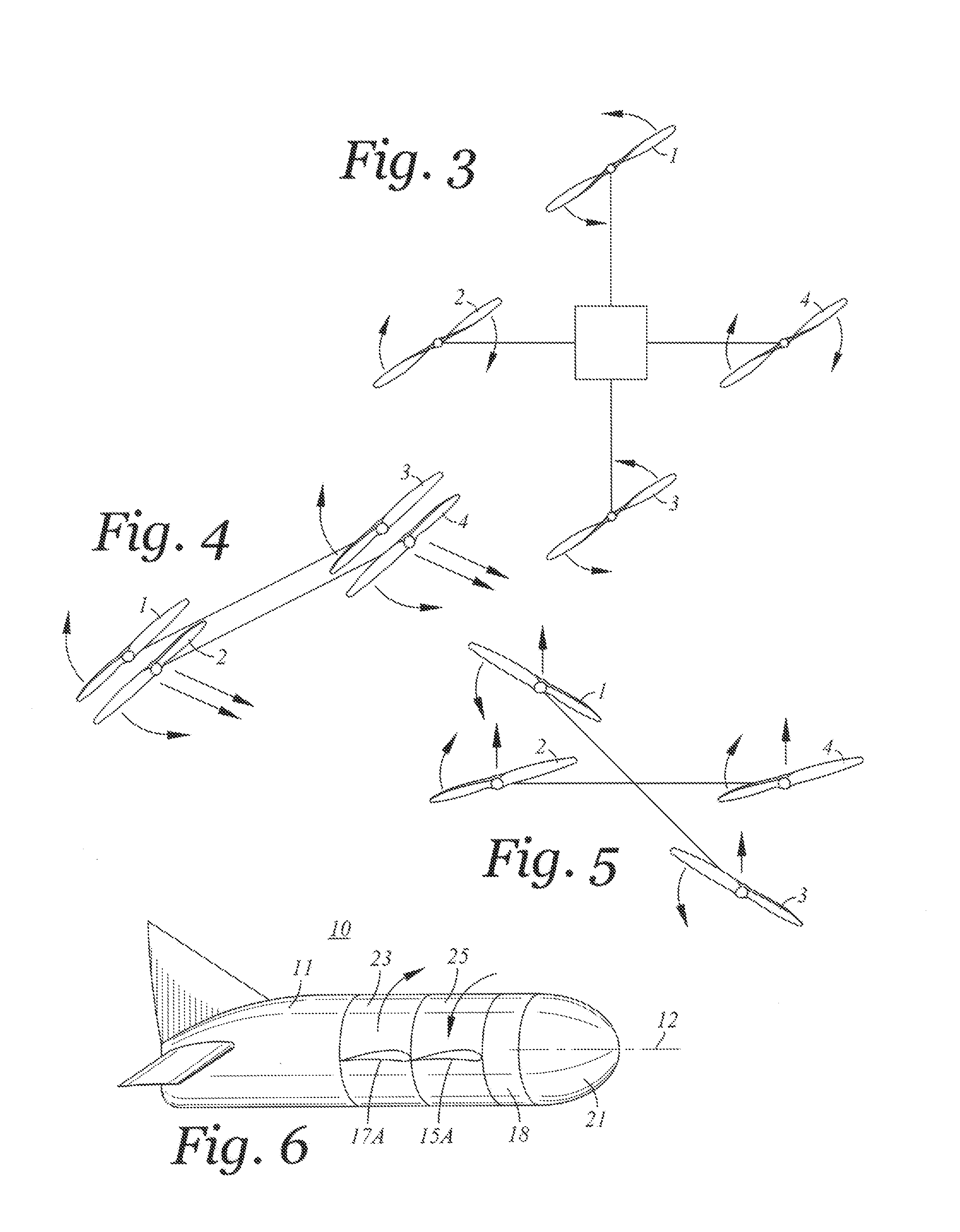
[0028]FIG. 1 illustrates one embodiment of a multi-engine aircraft that is convertible from a horizontal flight mode to a vertical flight mode in accordance with the present invention. As shown therein aircraft 10 includes an aircraft fuselage 11 and a pair of wings 13A, 13B. Each wing is formed of two separable portions, as described in more detail below. Wing 13A is formed to include wing segments 15A, 17A. Wing 13B is formed to include wing segments 15B, 17B. In the horizontal flight mode wing segment 15B is adjacent to and substantially is coplanar with wing segment 17B, and wing segment 15A is adjacent to and substantially coplanar with wing segment 17A. An aircraft propulsion unit is attached to each of the wing segments. Propulsion unit 1 is attached to wing segment 17A and propulsion unit 2 is attached to wing segment 15A. Propulsion unit 3 is attached to wing segment 17B and propulsion unit 4 is attached to wing segment 15B. Propulsion units 1 and 2 are in substantial axial...


PUM


Abstract

A multi-engine aircraft is disclosed which is convertible from horizontal flight mode to a vertical flight mode. The aircraft comprises an aircraft fuselage defining a fuselage longitudinal axis, and the first and second wing attached to the fuselage. Each wing defines first and second wing segments. The first segments are translatable about the fuselage longitudinal axis, from a horizontal mode position adjacent the second wing segments to vertical fight mode wherein the first wing segment are substantially offset from the second wing segments. An aircraft propulsion unit is attached to each of the first and second wing segments. The propulsion units attached to a common wing being disposed in substantial axial alignment when the aircraft operates in a horizontal flight mode, and being substantially offset when the aircraft operates in a vertical flight mode. A senor unit is connected to a forward portion of the fuselage.

Description

BACKGROUND[0001]The present invention relates to an aircraft, and more particularly an aircraft designed for horizontal as well as vehicle flight.[0002]In broad classification, aircraft are designated as fixed wing aircrafts or rotary wing aircraft. A fixed wing aircraft encompasses the bulk of commercial and military aircraft. Rotary wing aircraft traditionally encompass various types of helicopters and other vehicles where the propulsion system is primarily oriented for vertical lift, rather than horizontal flight, as is the case for a fixed wing aircraft.[0003]Various types of aircraft have been implemented or proposed wherein the propulsion system translates from a horizontal plane to a vertical plane, or where an engine thrust is vectored between a horizontal plane and a vertical plane.[0004]The ability of an aircraft to operate both in a horizontal flight mode and in a vertical lift / loitering mode can be advantageous, particularly in a certain application. Horizontal flight mo...

Claims


Application Information

Patent Timeline
IPC IPC(8): B64C3/32B64C3/38B64C29/00
CPCB64C3/32B64C3/38B64C29/0016B64C29/02B64C39/024B64U10/25B64U70/80B64U30/10B64U30/20B64U50/19B64U50/14B64C27/22B64C27/26B64C39/008
Inventor TIGHE, THOMAS S.
Owner NORTHROP GRUMMAN SYST CORP
Why Eureka
Try Eureka