Heating device of a PCV valve

a technology of pcv valve and heat exchanger, which is applied in the direction of engine cooling apparatus, combustion engines, machines/engines, etc., can solve the problems of affecting the efficiency of heat transfer from the conduit to the bush, the water component contained in the blowby gas may freeze, and the passage in the pcv valve may be blocked, so as to achieve efficient heat transfer and efficient heat transfer

Active Publication Date: 2015-08-13
KOJIMA PRESS IND CO LTD
View PDF8 Cites 4 Cited by
  • Summary
  • Abstract
  • Description
  • Claims
  • Application Information

AI Technical Summary

Benefits of technology

[0012]According to the heating device of a PCV valve of items (1)-(8) above, the PCV valve contacts the bush. The bush includes the outward protrusion. The outward protrusion has the curved surface contacting the outside surface of the conduit in the manner of a surface-to-surface contact. Therefore, the following technical advantages can be obtained:
[0013]When the conduit is heated by an engine cooling water, the bush contacting the conduit in the manner of a surface-to-surface contact is heated and the PCV valve contacting the bush is heated. Therefore, the PCV valve can be heated by the engine cooling water. Since the bush contacts the conduit in the manner of a surface-to-surface contact, the bush is heated more efficiently than in a case where the bush does not contact the conduit in the manner of a surface-to-surface contact.
[0014]According to the heating device of a PCV valve of item (2) above, since the bush and the conduit are welded to each other, heat transfer from the conduit to the bush is conducted efficiently.
[0015]According to the heating device of a PCV valve of item (5) above, since the bush and the conduit are covered with the cover, radiation of heat from the bush and the conduit is more suppressed than in a case where the bush and the conduit are not covered with the cover.

Problems solved by technology

Therefore, when the PCV valve is mounted to the oil separator, a heat from the engine is more difficult to be transmitted to the PCV valve via the oil separator than in a case where the oil separator is made from metal.
As a result, when an ambient temperature is low, a water component contained in the blowby gas may freeze whereby a blowby gas passage in the PCV valve may be blocked by ice.

Method used


Image

  • Heating device of a PCV valve
  • Heating device of a PCV valve
  • Heating device of a PCV valve

Examples


Embodiment Construction

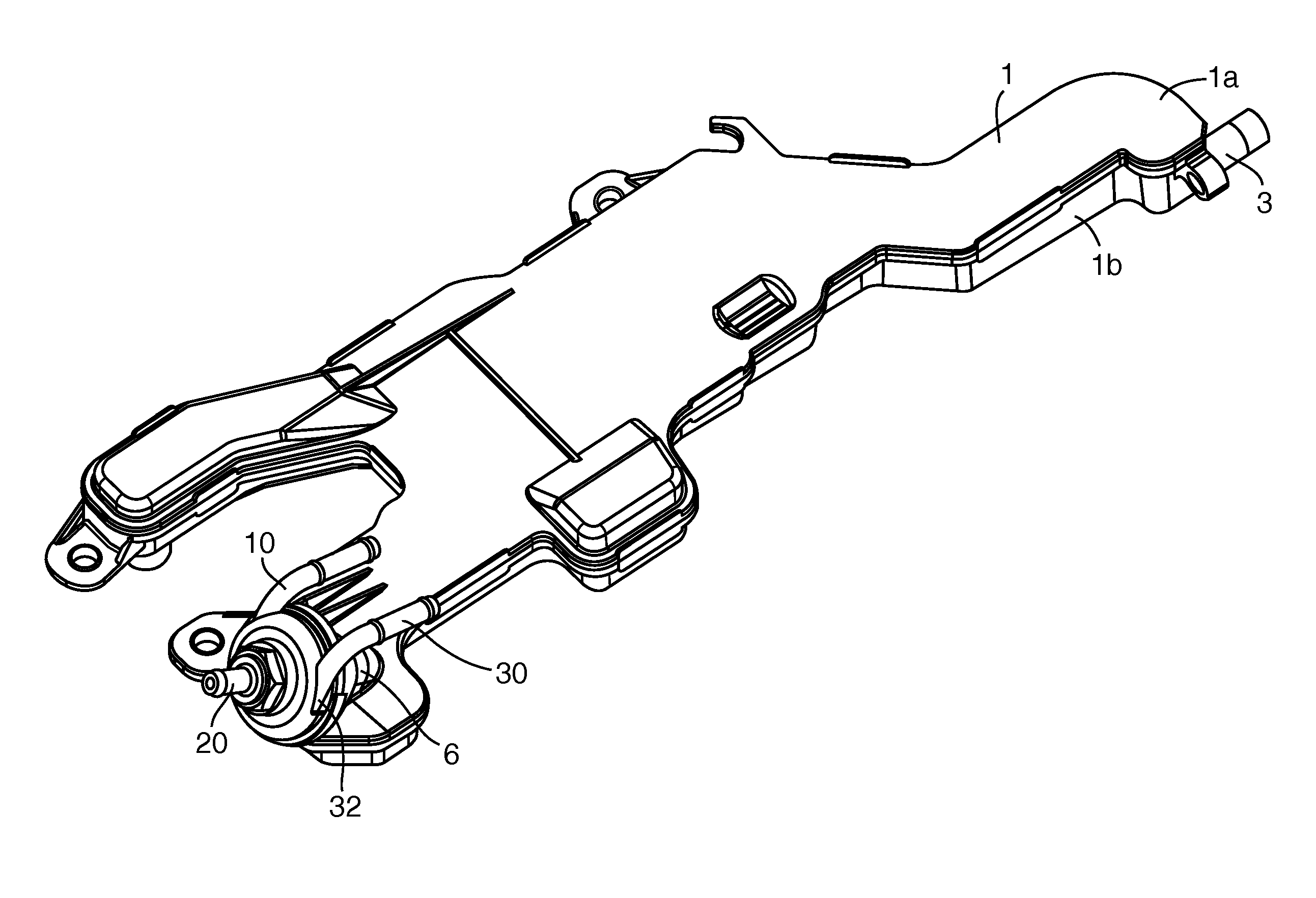
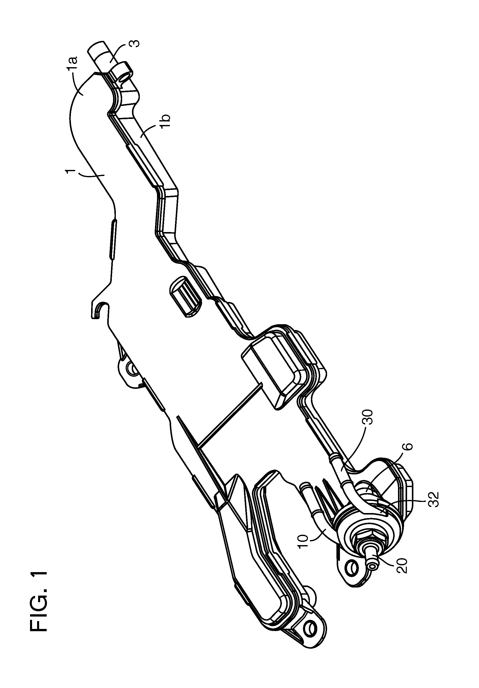
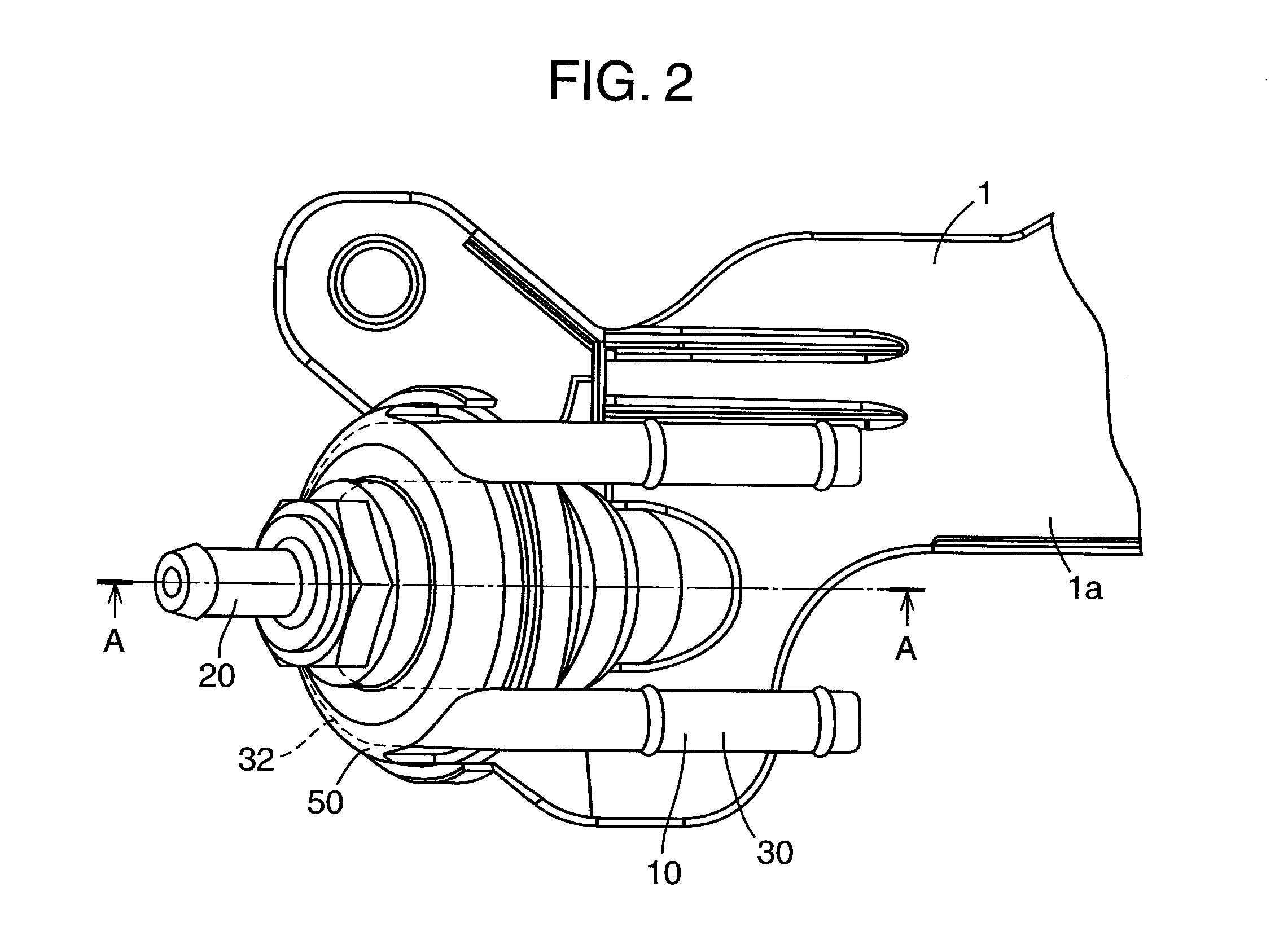
[0021]A heating device of a PCV valve according to an embodiment of the present invention will be explained below with reference to the drawings. As illustrated in FIG. 1, the heating device 10 of a PCV valve according to an embodiment of the present invention is a device heating a PCV valve 20 mounted to an oil separator 1 made from resin.

[0022]As illustrated in FIG. 5, the oil separator 1 is provided so as to separate oil 61 from a blowby gas 60 leaking to a crankcase (not shown) of a vehicle engine (not shown). The oil 61 separated from the blowby gas is caused to flow to the crankcase. As illustrated in FIG. 1, the oil separator 1 includes an upper casing 1a and a lower casing 1b. The upper casing 1a and the lower casing 1b are manufactured separately from each other and fixed to each other. The upper casing 1a and the lower casing 1b are fixed to each other by vibration welding or an adhesive.

[0023]As illustrated in FIG. 5, the oil separator 1 includes a chamber 2, a gas inlet ...


PUM


Abstract

A heating device of a PCV valve includes a PCV valve, a conduit and a bush. The PCV valve contacts the bush. The bush includes an outward protrusion. The outward protrusion includes a curved surface contacting an outside surface of the conduit in a manner of a surface-to-surface contact. Therefore, when the conduit is heated by engine cooling water, the bush contacting the conduit in the manner of a surface-to-surface contact is heated and the PCV valve contacting the bush is heated. Therefore, the PCV valve can be heated by the engine cooling water.

Description

TECHNICAL FIELD[0001]The present invention relates to a heating device for heating a positive crankcase ventilation (PCV) valve mounted to an oil separator made from resin.BACKGROUND OF THE INVENTION[0002]Blowby gas includes gas leaking from a clearance between a cylinder and a piston to a crankcase of an engine. Fuel economy is improved by leading the blowby gas to an intake passage. Further, since a pressure inside the crankcase can be made to a negative pressure, a pumping loss of a piston can be decreased. An engine oil mist is included in the blowby gas and the oil is separated from the blowby gas by an oil separator. The blowby gas from which the oil is separated is caused to flow to the intake passage. The amount of the blowby gas flowing to the intake passage is regulated by a PCV valve.[0003]For decreasing manufacturing costs, the oil separator is made from resin. Therefore, when the PCV valve is mounted to the oil separator, a heat from the engine is more difficult to be t...

Claims


Application Information

Patent Timeline
Patent Type & Authority Applications(United States)
IPC IPC(8): F01M13/00F01P11/04F01M13/04
CPCF01M13/0011F01M13/04F01M2013/0027F01M2013/0044F01P11/04F01M13/00
Inventor HASEGAWA, NAOHIRO
Owner KOJIMA PRESS IND CO LTD
Why Eureka
Try Eureka