Method and device for verification and/or calibration of a pressure sensor

a pressure sensor and verification method technology, applied in the direction of measurement devices, fluid pressure measurement, instruments, etc., can solve the problems of inability to provide continuous verification, linear regressions will not work properly, and high time and manpower requirements to provide a reference sensor, so as to achieve reliable verification or calibration, the effect of high precision

Active Publication Date: 2015-08-13
SARTORIUS STEDIM BIOTECH GMBH
View PDF7 Cites 11 Cited by
  • Summary
  • Abstract
  • Description
  • Claims
  • Application Information

AI Technical Summary

Benefits of technology

[0024]The calibration of the pressure sensor is exact, since the differences between the measured pressures p0, p1, and p2 are only dependent on the volumes of the vessels and the volume of the fluid connection or fluid lines connecting the vessels and the pressure sensor. These volumes can be determined with a high precision and, thus, the verification or calibration is reliable.

Problems solved by technology

Since the reading of the pressure sensor may be prone to some time drifts during use of the apparatuses, it is necessary to verify, whether the readings of the pressure sensor are reliable or whether the pressure sensor must be replaced by a new one.
However, high efforts of time and manpower are required to provide a reference sensor and perform the verification test.
Thus, this procedure is not suitable to provide a continuous verification whether the pressure sensor is possibly affected by a time drift phenomenon.
It is a problem to provide a more quick and reliable test method and a corresponding test device to perform a verification or calibration test of the pressure sensor.
However, a regression coefficient lower than a predetermined value, for example 0.95 or 0.9, might indicate that the linear regressions will not work properly.
In this case, a warning might be generated that the pressure sensor is not reliable.

Method used


Image

  • Method and device for verification and/or calibration of a pressure sensor
  • Method and device for verification and/or calibration of a pressure sensor
  • Method and device for verification and/or calibration of a pressure sensor

Examples


Embodiment Construction

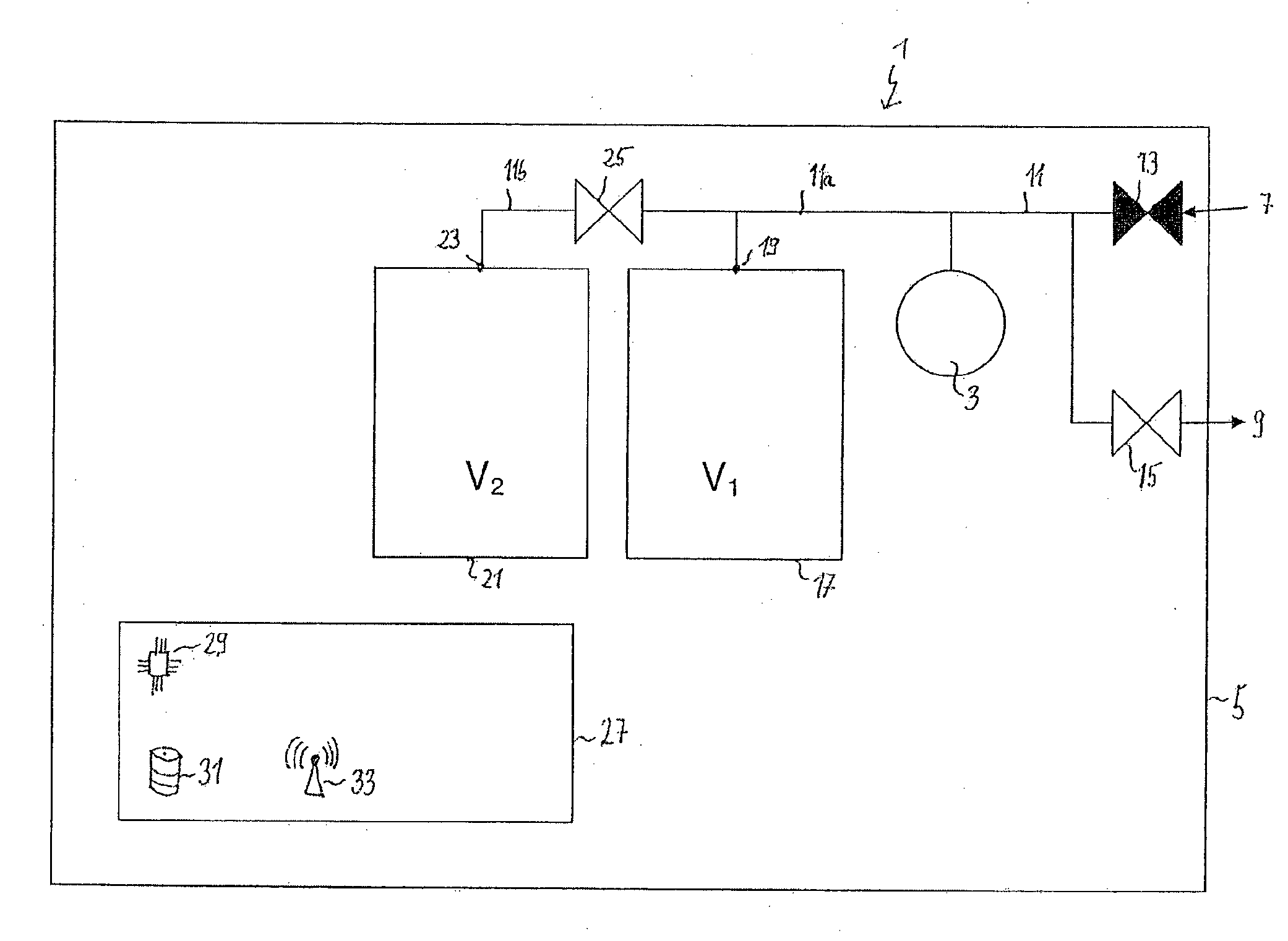
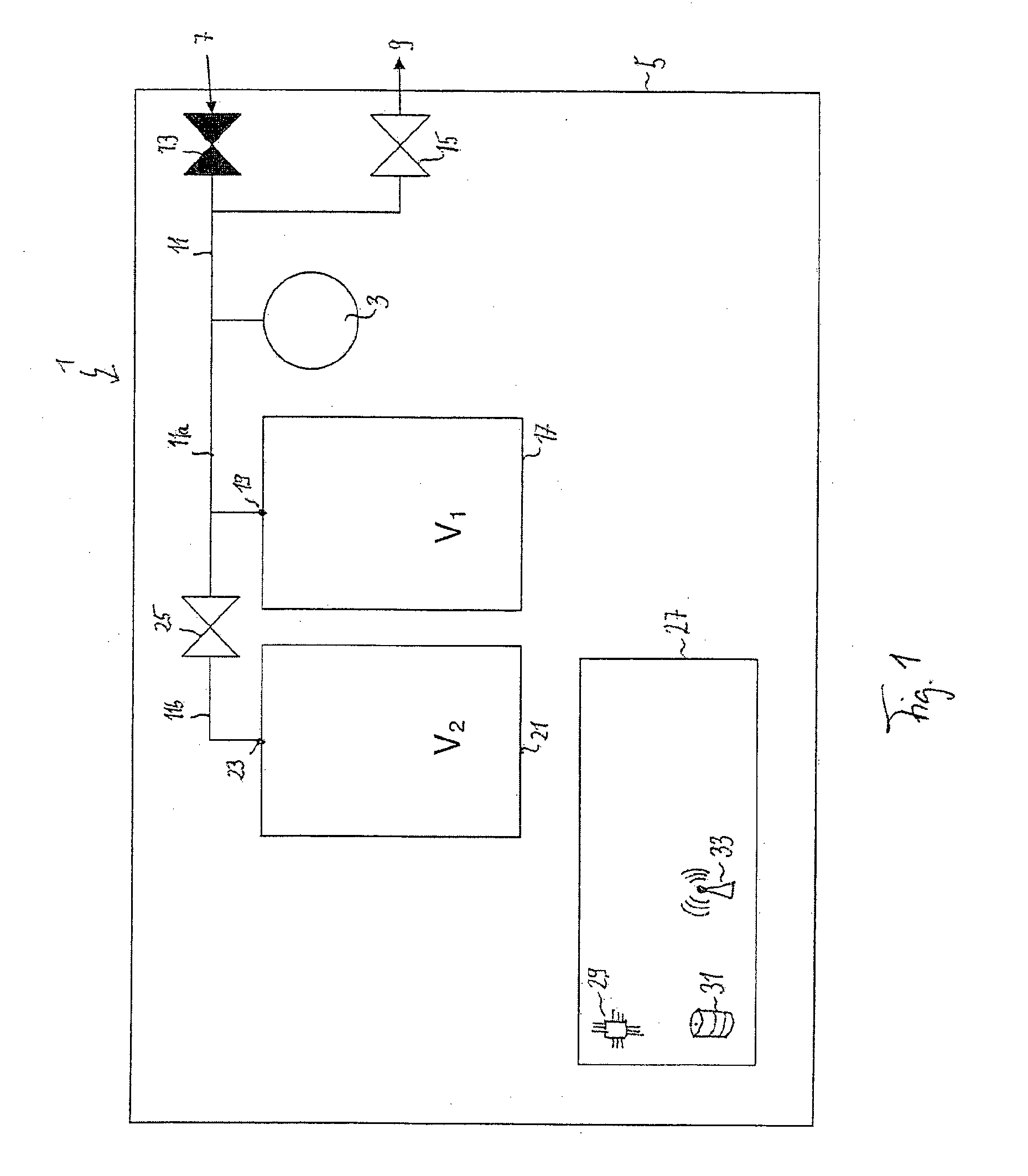
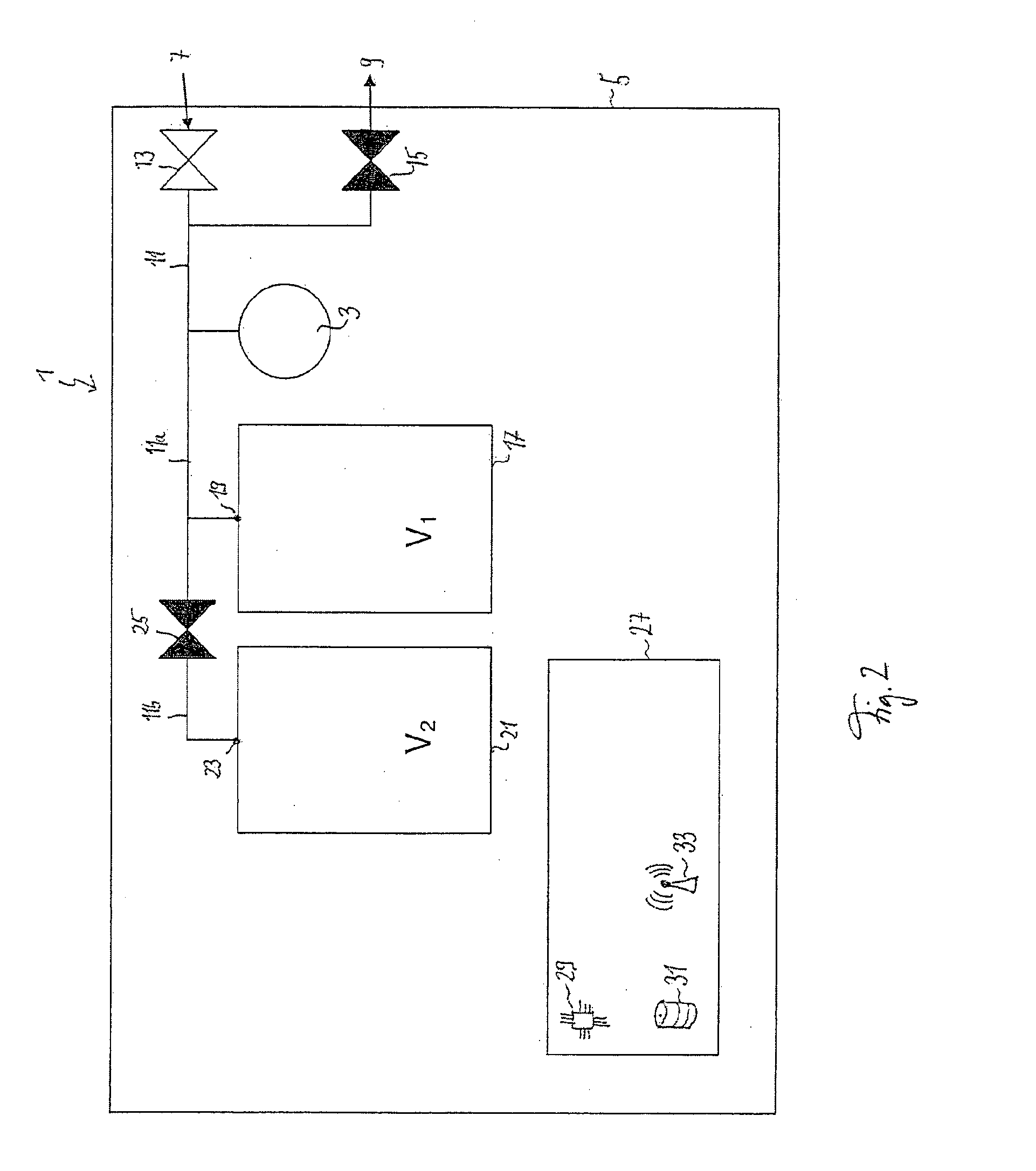
[0088]FIGS. 15-16 show diagrams illustrating the correlation of measured fluid pressures and predicted fluid pressures. FIGS. 1 to 7 show a test device 1 for carrying out an automatic verification and / or calibration of a pressure sensor 3. The test device 1 can be part of a test apparatus, for example a test apparatus for performing an integrity test on a filter device (not shown) or any other apparatus, which must comprise a pressure sensor 3 in order to measure a fluid pressure. Therefore, the test device 1 may be located in a housing 5, which further comprises additional electric, electronic, mechanic and / or electromechanic components, which are not intended to perform the verification and / or calibration of the pressure sensor 3, but are provided to perform further tasks needing the pressure sensor 3.

[0089]The test device 1 comprises a fluid inlet 7 and a fluid outlet 9. The fluid inlet 7 and / or the fluid outlet 9 can be formed as a fluid connector in the housing 5. The fluid inl...


PUM

PropertyMeasurementUnit
pressuresaaaaaaaaaa
pressuresaaaaaaaaaa
stabilization timeaaaaaaaaaa

Abstract

A method for calibrating a pressure sensor includes connecting the pressure sensor to first and second fluid storage vessels; providing an initial fluid pressure at the pressure sensor and at the fluid storage vessels; and carrying out a pressure measurement of the initial fluid pressure at a time t0. The method then disconnects the second fluid storage vessel from the pressure sensor and the first fluid storage vessel; provides a first fluid pressure at the second fluid storage vessel; and carries out a pressure measurement of the first fluid pressure at a time t1. The method then connects the second fluid storage vessel with the pressure sensor and the first fluid storage vessel, so that a second fluid pressure between the initial and first fluid pressures is provided at the pressure sensor; and carries out a pressure measurement of the second fluid pressure at a time t2.

Description

BACKGROUND[0001]1. Field of the Invention[0002]The invention relates to a method for verifying and / or calibrating a pressure sensor and a device for automatically carrying out the verification and / or calibration of the pressure sensor. The invention likewise relates to a computer program product for automatically carrying out the method.[0003]2. Description of the Related Art[0004]Various apparatuses for production or testing comprise one or more pressure sensor for reading the pressure of a fluid, such as a gas, a liquid or a mixture thereof, for example to control the pressure in a biochemical process container or to verify filter devices. Since the reading of the pressure sensor may be prone to some time drifts during use of the apparatuses, it is necessary to verify, whether the readings of the pressure sensor are reliable or whether the pressure sensor must be replaced by a new one.[0005]In order to perform a verification of the pressure sensor it is required to compare the rea...

Claims


Application Information

Patent Timeline
Patent Type & Authority Applications(United States)
IPC IPC(8): G01L27/00
CPCG01L27/002G01L27/005
Inventor STERING, MAGNUS
Owner SARTORIUS STEDIM BIOTECH GMBH
Why Eureka
Try Eureka