Distance measurement apparatus, imaging apparatus, distance measurement method, and program
- Summary
- Abstract
- Description
- Claims
- Application Information
AI Technical Summary
Benefits of technology
Problems solved by technology
Method used
Image
Examples
Example
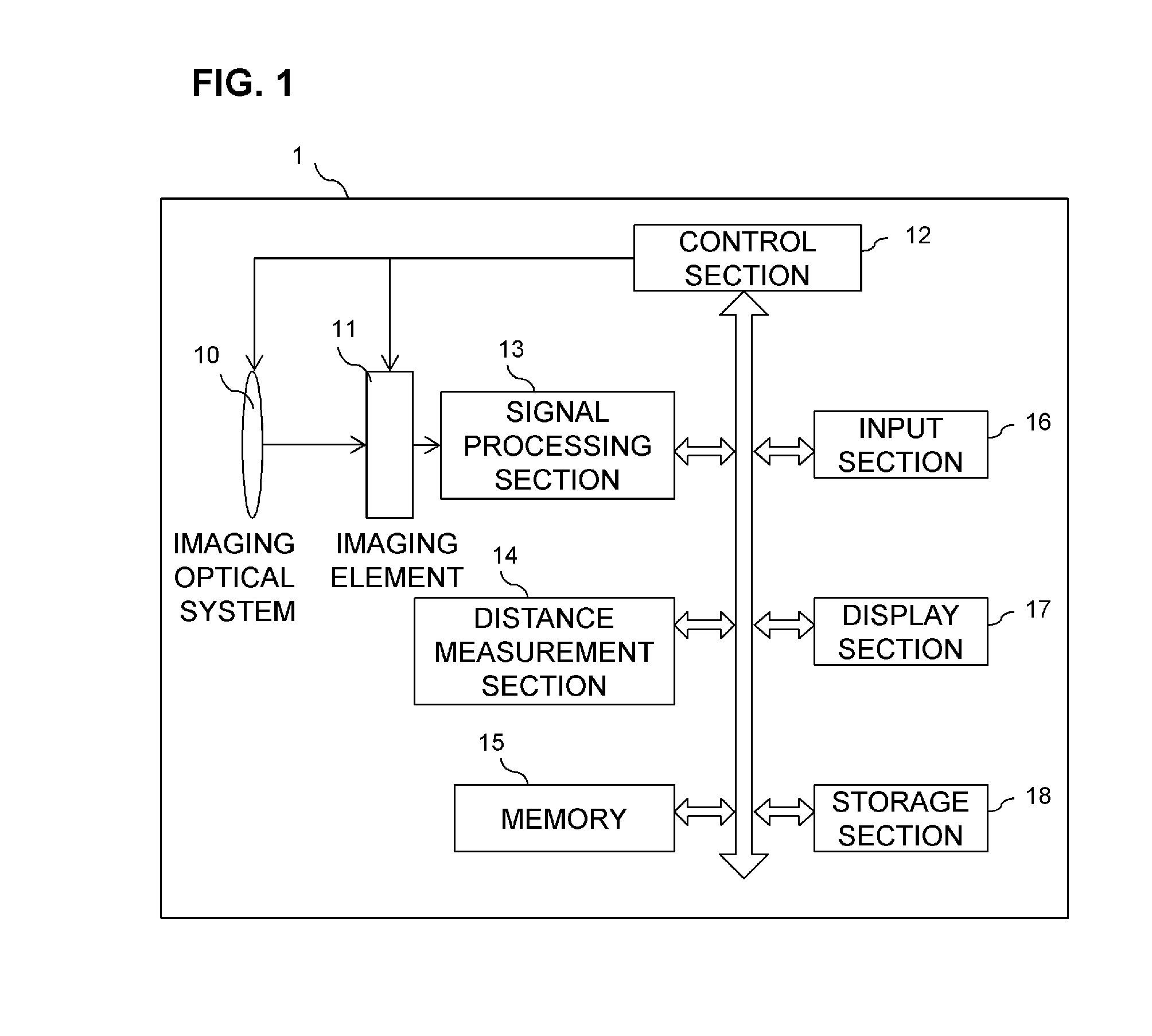
[0040]In the first embodiment, the second image is captured with focus position changed. For example, the first image is captured in accordance with autofocus so as to allow a main object to be focused on. The second image is captured with the focus position pre-changed by a specified amount so as to blur the main object.
[0041]In this regard, desirably, shutter speed is increased and image capturing intervals are reduced for accurate distance measurement. This is because the adverse effect of camera shake or object shake decreases with increasing shutter speed and decreasing image capturing intervals. However, when sensitivity is increased in order to increase the shutter speed, the adverse effect of noise may be more serious than the adverse effect of camera shake, and thus, the appropriate shutter speed needs to be set in view of sensitivity.
[0042]When the two images are captured, the captured images are each processed by the signal processing section so as to be suitable for dist...
Example
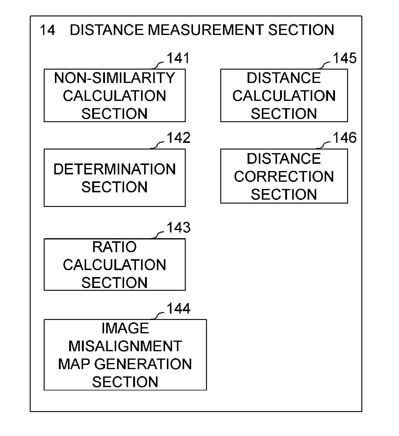
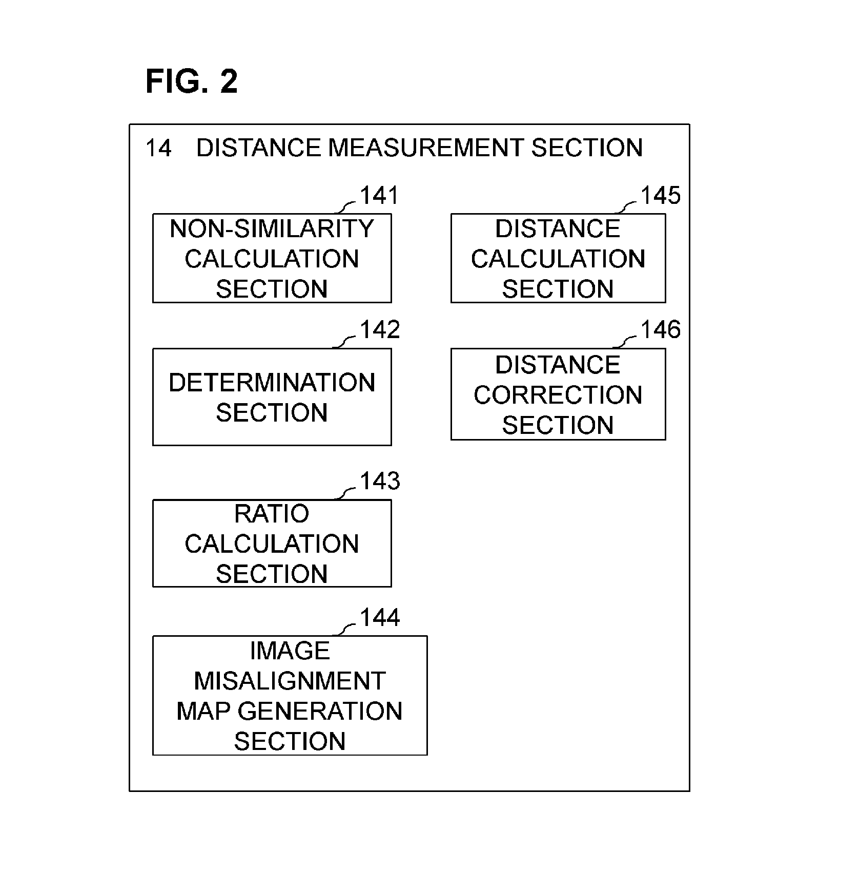
[0069]Now, a second embodiment of the present invention will be described. The second embodiment differs from the first embodiment in that, in the distance measurement based on the DFD method, the image capturing parameter to be changed is not the focus position but the F number and in that, besides the distance measurement, determination for image misalignment is performed. A configuration of an imaging apparatus according to the second embodiment is basically identical to the configuration in Embodiment 1 (FIG. 1 and FIG. 2). The main difference is that a distance measurement section 14 performs detection of image misalignment before distance calculation rather than simultaneously performing the detection of image misalignment and the distance calculation.
[0070]The difference in processing from the first embodiment will be described below. FIG. 5 is a flowchart depicting a flow from image capturing to an image misalignment determination process and a distance map generation proces...
Example
[0082]A third embodiment of the present invention is an embodiment added with determination of whether image misalignment is occurring particularly in a region of interest. A configuration of an imaging apparatus in the third embodiment is similar to the configuration in the first and second embodiments.
[0083]Differences in processing from the first embodiment will be described below. FIG. 8 is a flowchart depicting a flow of a pixel misalignment determination process in the third embodiment.
[0084]Processing in steps S61 to S66 in the first embodiment is similar to the processing in steps S21 to S26 and will thus not be described below. The processing in steps S61 to S66 completes calculation of distance information and determination of whether or not image misalignment is present, for all the pixels.
[0085]In step S66, a region of interest in which a photographer and an observer are interested is extracted from the images. This region-of-interest extraction process may be executed b...
PUM
 Abstract
Description
Claims
Application Information
 - R&D
- Intellectual Property
- Life Sciences
- Materials
- Tech Scout
- Unparalleled Data Quality
- Higher Quality Content
- 60% Fewer Hallucinations
Browse by: Latest US Patents, China's latest patents, Technical Efficacy Thesaurus, Application Domain, Technology Topic, Popular Technical Reports.
© 2025 PatSnap. All rights reserved.Legal|Privacy policy|Modern Slavery Act Transparency Statement|Sitemap|About US| Contact US: help@patsnap.com


