
Method and device to regulate the electric motor of a handheld power tool

a technology of electric motor and power tool, which is applied in the direction of motor/generator/converter stopper, dynamo-electric converter control, instruments, etc., can solve the problems of excessive carbon wear and reduce the service life of mechanically commutated motors. , to achieve the effect of improving the regulation of electric motor

Inactive Publication Date: 2015-08-13
HILTI AG
View PDF6 Cites 6 Cited by
  • Summary
  • Abstract
  • Description
  • Claims
  • Application Information

AI Technical Summary

Benefits of technology

The present invention is about improving the regulation of the electric motor of a handheld power tool to prevent excessive carbon wear and increase the service life of the tool. This is achieved by systematically varying the actual speed of the electric motor, especially by a certain operating point determined by the user. The prevention of resonance effects on the commutators of mechanically commutated electric motors is achieved through a random generator which yields a sequence of varying periods of time. The use of specified values determined by a random generator further reduces the resonance effect on the commutators.

Problems solved by technology

However, modern speed regulators sometimes work so precisely that resonance effects can cause the commutators of mechanically commutated motors to run out-of-round.
This can excessively increase the carbon wear of the mechanically commutated motors.
This increase in the carbon wear reduces the service life of the mechanically commutated motor of the handheld power tool.

Method used


Image

  • Method and device to regulate the electric motor of a handheld power tool
  • Method and device to regulate the electric motor of a handheld power tool
  • Method and device to regulate the electric motor of a handheld power tool

Examples


Embodiment Construction

[0030]Unless otherwise indicated, identical or functionally equivalent elements are designated by the same reference numerals in the figures.

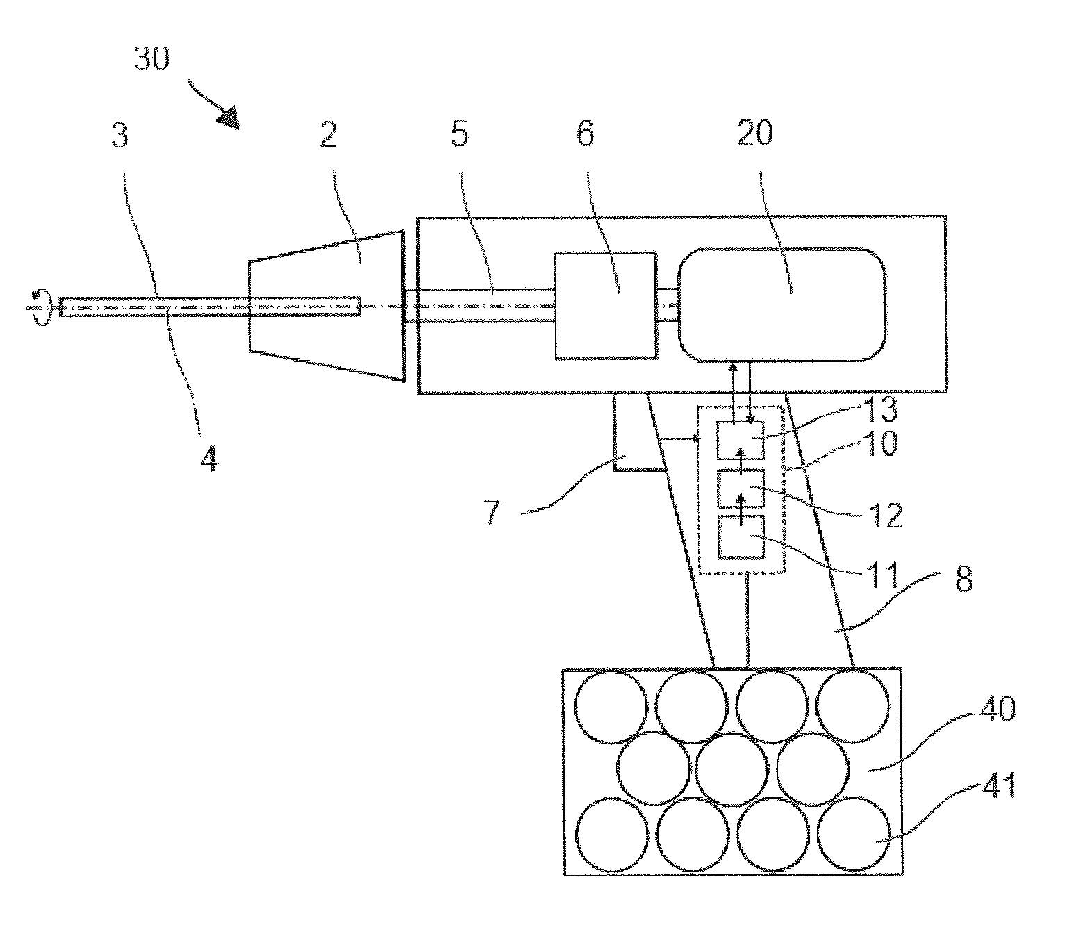
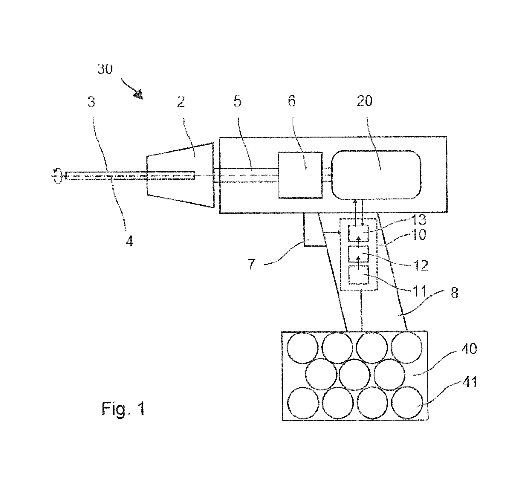
[0031]FIG. 1 shows by way of an example a handheld power tool 30, for instance, an electric screwdriver. The handheld power tool has a tool socket 2 into which a tool 3 can be inserted or attached. The tools are, for example, a screw bit, a drill bit, a grinding disk or a saw blade. An electric motor 20 drives the tool socket 2, here for instance, so as to rotate around a working axis 4. A powertrain situated between the tool socket 2 and the electric motor 20 can comprise a spindle 5, a gear 6 and additional components, e.g. a torque coupler, an eccentric wheel.

[0032]A user starts the handheld power tool 30 by actuating a switch 7. The switch 7 is preferably located on a handle 8 by means of which the user can hold and guide the handheld power tool 30. In response to the actuation, a control unit 10 supplies power to the electric motor 20. An ...


PUM


Abstract

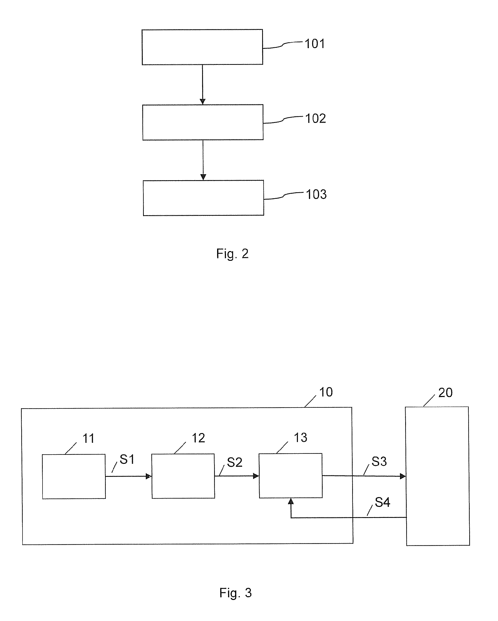
A method to regulate the electric motor of a handheld power tool, the method encompassing the following steps: prescribing a target speed for the electric motor, varying the prescribed target speed—each time after a certain period of time has lapsed—by a value within a certain variation range in order to supply a varied target speed, and regulating an actual speed of the electric motor to the supplied varied target speed.

Description

[0001]The present invention relates to a method and to a device to regulate the electric motor of a handheld power tool. The invention also relates to a control unit for a handheld power tool having such a device as well as to such a handheld power tool, especially an electric handheld power tool such as, for instance, an electric screwdriver or a handheld power drill.BACKGROUND[0002]The electric motor of the handheld power tool is normally regulated to a target speed by means of a speed regulator.[0003]However, modern speed regulators sometimes work so precisely that resonance effects can cause the commutators of mechanically commutated motors to run out-of-round. This can excessively increase the carbon wear of the mechanically commutated motors. This increase in the carbon wear reduces the service life of the mechanically commutated motor of the handheld power tool.SUMMARY OF THE INVENTION[0004]It is an object of the present invention to improve the regulation of the electric mot...

Claims


Application Information

Patent Timeline
IPC IPC(8): H02P7/24H02K7/14
CPCH02P7/245H02P2007/0088H02K7/145B25F5/00B25B21/00H02P31/00
Inventor FORSTNER, MARKUSJAKOB, MANFRED
Owner HILTI AG
Learn More