Electronic countermeasures transponder system

a transponder system and countermeasure technology, applied in the field of radio frequency signalling and telecommunications, can solve the problem of limited space effect of the ecm

Active Publication Date: 2015-08-13
SKY IND
View PDF4 Cites 39 Cited by
  • Summary
  • Abstract
  • Description
  • Claims
  • Application Information

AI Technical Summary

Benefits of technology

[0007]While the detailed embodiments described below assume the use of an ECM system, more generally, any of the embodiments described can be used in the context of a generalized primary communications system. An ECM system can be considered a specific example of such a primary communications system.

Problems solved by technology

In most cases, the effectiveness of the ECM is limited to a volume of space, and protectees must remain inside this space to benefit from the protection provided by the ECM.

Method used


Image

  • Electronic countermeasures transponder system
  • Electronic countermeasures transponder system
  • Electronic countermeasures transponder system

Examples


antenna embodiment

Shared Antenna Embodiment

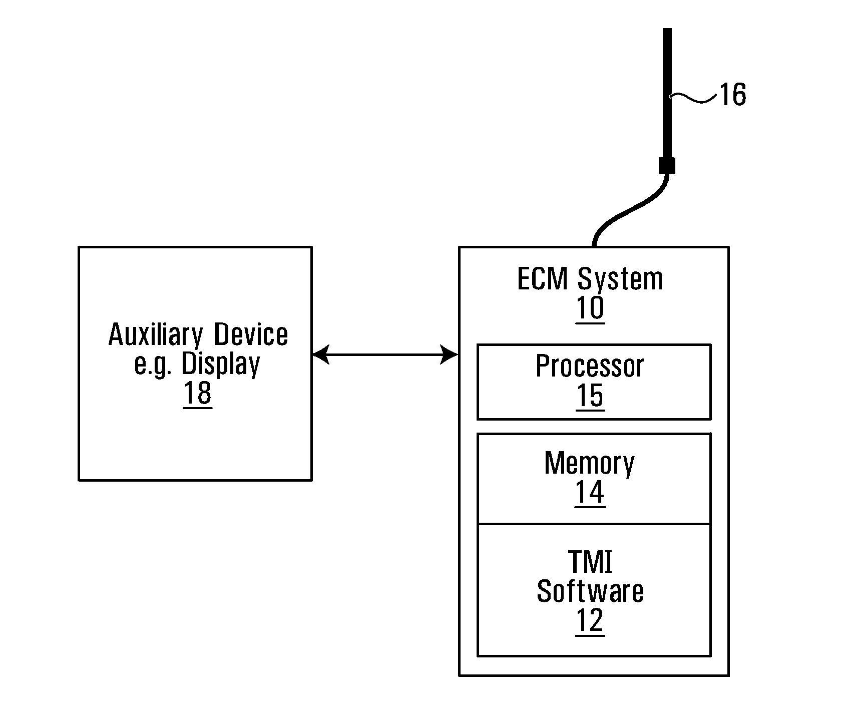
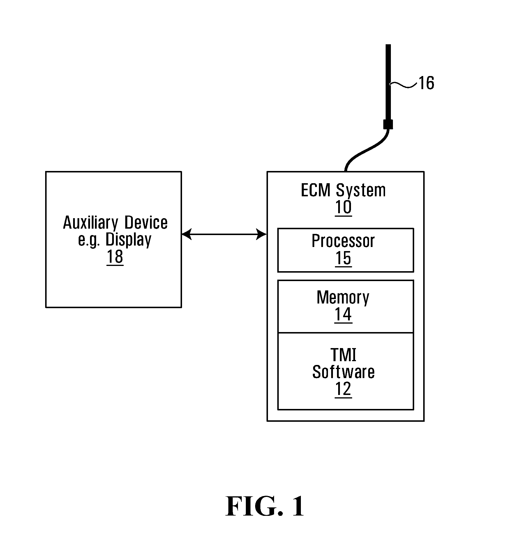
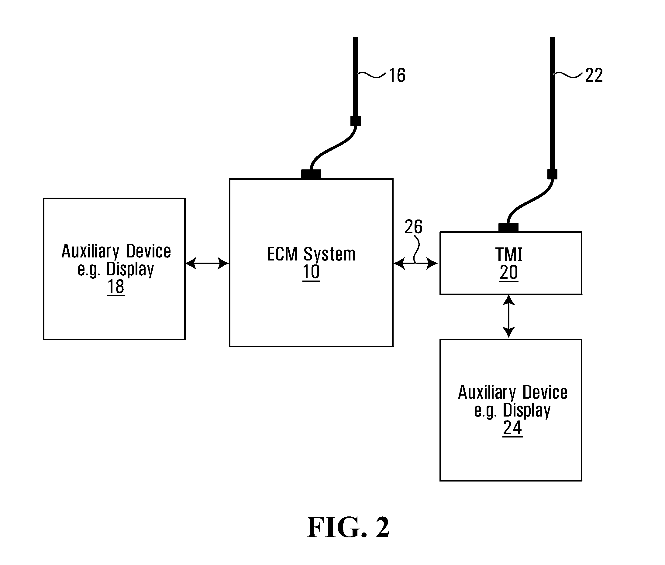
[0034]In some embodiments, the ECM system and parts or all of the TMI are physically separate, but share an antenna, so that range measurements are intrinsically relative to the origin of the ECM signal, and so are relative to the spatial origin of the ECM protection. This embodiment confers the shared-antenna advantages already mentioned for the embodiment in which the TMI function is integrated as software in the ECM system. An example is depicted in FIG. 3, which is the same as FIG. 2, but for the fact that the TMI 20 is connected to the ECM system antenna 16 through a power combiner / splitter 28, such that RF signals from the antenna are fed to both the ECM system 10 and the TMI 20, and signals from both the ECM system and the TMI are fed to the same antenna.

Range Estimation Relative to ECM Antenna Location

[0035]As detailed above, in some embodiments, range estimation relative to ECM antenna location is provided. Broadly speaking, the range between the EC...

case 1

ECM System, Stationary or Nearly Stationary Transponder

[0099]In some embodiments the location of a transponder which is known or believed to be stationary or nearly stationary is triangulated by a moving ECM system. In some embodiments, the method proceeds in the following steps, where example geometry is illustrated in FIG. 5. The main elements are the ECM system 200, and a transponder 201, an example of which is an RFID tag. The solution is the (xT,yT) coordinates of the transponder 202 at its current location.

[0100]Step 1: The ECM system 200 measures the range 201 to the transponder 202 as the ECM system traverses a path 203. To illustrate the principle by which multiple measurements are used, a first range measurement occurs at a general point P1 204 defined relative to a coordinate system having origin 217, for example a coordinate system whose origin 217 is coincident with an initial ECM position. Position P1=(x1, y1) can be thought of as changes of position Δx1, Δy1 relative ...

case 2

nary or Nearly Stationary ECM System, Moving Transponder

[0111]In some embodiments the trajectory of a moving transponder is triangulated by a stationary or nearly stationary ECM system. In such scenarios the ECM system estimates the change of transponder position between two range observations. The general problem arrangement is illustrated in FIG. 6.

[0112]The solution is a line L1300 which is believed to hold the true current transponder position (x1T, y1T) 301, relative to an earlier estimated position of the transponder (x0T, y0T) 302. The line L1300 is calculated by using 1) one or more range measurements made by an ECM system 303 embedded in a world coordinate frame 309, and 2) lower and upper bounds on the average speed of the transponder 302 between the initial observation time t0 and a later time t0+Δt at which the transponder position is to be estimated. FIG. 6 illustrates the case of a single range measurement at time Δt later. Average speed is used here as a trivial examp...


PUM


Abstract

A system is provided that has an ECM (electronic counter measures) system and a transponder monitor connected to or forming part of the ECM system. The system monitors for a transponder signal from a remote transponder. The system determines information, such as transponder location, based on the transponder signal and makes use of the information in the ECM system and/or the system extracts encoded information contained in the transponder signal, such as information about a transponder owner, such as status of consumables, medical status. The ECM system may have a reactive jammer that is used both for a reactive jamming function, and as the transponder monitor function.

Description

CROSS-REFERENCE TO RELATED APPLICATIONS[0001]This application also claims the benefit of, and is a continuation of PCT Application Serial No. PCT / CA2013 / 050823, filed on Oct. 31, 2013, which in turn claims the benefit of U.S. Provisional Patent Application Ser. No. 61 / 720,690 filed on Oct. 31, 2012. The entire contents of these related patent applications are incorporated in their entirety herein by reference.FIELD OF THE PRESENT INVENTION[0002]The present invention pertains to the field of radio frequency signalling and telecommunications, with electronic countermeasures as a specific example.BACKGROUND OF THE PRESENT INVENTION[0003]This patent application is related in part to patents concerning estimation of the effective range of a communications system, including U.S. Pat. No. 8,184,036 B2, Canada patent 2,624,233, Australia patent 2008201111, and United Kingdom patent GB2449151, the contents of which are hereby incorporated by reference in their entireties.[0004]There are cert...

Claims


Application Information

Patent Timeline
Patent Type & Authority Applications(United States)
IPC IPC(8): H04K3/00G01S7/38
CPCH04K3/65G01S7/38H04K3/40H04K3/92H04K2203/22H04K2203/36H04K2203/32H04K2203/20H04K2203/24G01S13/74F41H11/02H04K3/42H04K3/44H04K3/45H04K3/94H04K2203/34H04K3/28
Inventor SHAWN, CHARLAND
Owner SKY IND
Why Eureka
Try Eureka