
User scheduling and beamformer design method, apparatus, and storage medium based on two-stage beamformer for massive MIMO downlink

a beamformer and user technology, applied in the field of user scheduling and beamformer design methods, apparatuses, storage media for multi-user multi-input and multi-output (mimo) downlink, can solve the problems of severe sum rate performance degradation and insufficient sum rate performance, and achieve better date rate performance and feedback amount

Active Publication Date: 2015-08-13
KOREA ADVANCED INST OF SCI & TECH
View PDF3 Cites 26 Cited by
  • Summary
  • Abstract
  • Description
  • Claims
  • Application Information

AI Technical Summary

Benefits of technology

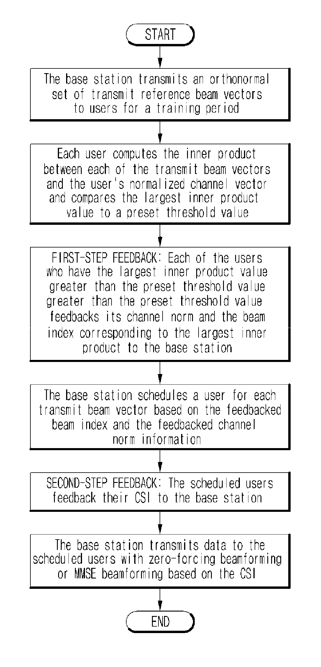
The patent text describes a method for selecting and refining multi-user beams in wireless communication networks with a minimum of feedback. The method uses a set of orthonormal reference beams and channels from each user to select roughly orthogonal users with large channel norms. These users are then further optimized using post-user-selection multi-user beamforming based on the channels from the scheduled users. This approach achieves full multi-user beamforming performance with far less feedback. The technical effect of this method is to improve the efficiency and performance of wireless communication networks with a minimum of feedback.

Problems solved by technology

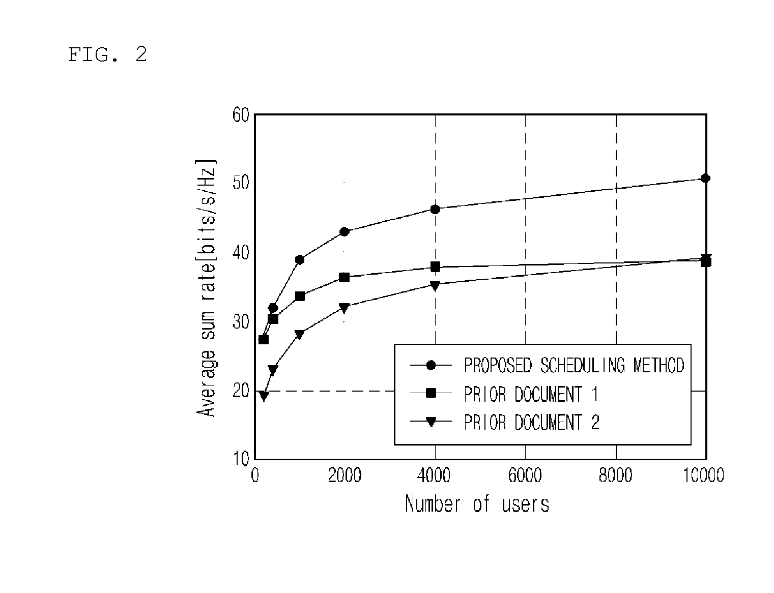
Hence, it can be considered optimal only when a very large number of users are present, but it is not optimal in terms of sum rate itself and its sum rate performance degradation is severe in the range of the realistic range of user number.

Method used


Image

  • User scheduling and beamformer design method, apparatus, and storage medium based on two-stage beamformer for massive MIMO downlink
  • User scheduling and beamformer design method, apparatus, and storage medium based on two-stage beamformer for massive MIMO downlink
  • User scheduling and beamformer design method, apparatus, and storage medium based on two-stage beamformer for massive MIMO downlink

Examples


Embodiment Construction

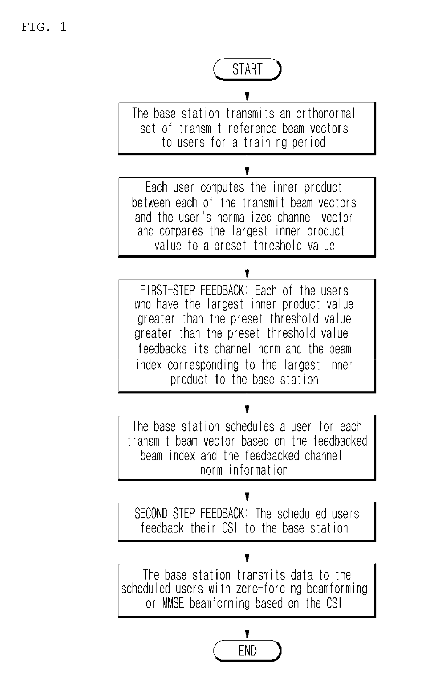
[0024]Embodiments of the present invention are described with reference to the accompanying drawing FIG. 1. In the following description of the present invention, detailed descriptions of known functions and configurations which are deemed to make the gist of the present invention obscure will be omitted.

[0025]Further, in the present specification, the term “user” denotes a user terminal, and thus the user may be construed as the user terminal. the method of the present invention is implemented by a processor of a base station.

[0026]For the explanation purpose, we consider the following multiple-input single-output (MISO) channel model:

ygk=hgkHx+ngk=hgkH[V1, . . . ,VG]diag(W1, . . . ,WG)d+ngk

where x is the transmit signal vector, ygk is the received signal at user k of group g, and ngk is the noise vector at user k of group g. Here, we assume two stage beamforming x=[V1, . . . , VG]diag(W1, . . . , WG)d, where {V1, . . . , VG} are the pre-beamformers separating different groups, {W...


PUM


Abstract

Disclosed herein are a user scheduling and beamformer design method, apparatus, and storage medium for multi-user MIMO downlink based on two-stage beamforming or single-stage beamforming. The user scheduling and beamformer design method includes 1) a two-step feedback approach, 2) the use of orthonormal reference beam vectors, 3) computation of the angle between the user's channel vector and each of the orthonormal reference beam vectors, 4) first-step feedback of the reference beam index to which the user's channel vector's angle is less than a certain threshold and feedback of the user's channel vector's norm, 5) selection of roughly orthogonal users with large channel norm based on the use of reference beam vectors and the channel norm feedback, 6) second-step feedback of the channel state information (CSI) from the scheduled users, 7) design of multi-user downlink beamformer for the scheduled users based on the second-step feedback of the CSI of the scheduled users. The main key point of this invention is that in the first step of user selection, we propose to use the channel norm or noise-plus-interference-divided channel norm as the feedback quantity and we propose to use only the angle between each of the reference beam vectors and the user's channel vector to identify the closest reference beam vector.

Description

CROSS-REFERENCE TO RELATED APPLICATION[0001]This application claims the benefit of Korean Application No. 10-2014-0014598 filed Feb. 10, 2014, the entire contents of which are incorporated herein by reference.BACKGROUND OF THE INVENTION[0002]1. Field of the Invention[0003]The present invention generally relates to a user scheduling and beamformer design method, apparatus, and storage medium for multi-user multiple-input and multiple-output (MIMO) downlink based on two-stage MIMO beamforming as well as conventional single-stage MIMO beamforming.[0004]2. Description of the Related Art[0005]In wireless communication, the demand for high data rates has increased, and the necessity for the improvement of frequency efficiency has rapidly increased. In order to meet such necessities, a massive MIMO system in which a large number of antennas are employed into a base station to improve frequency efficiency is regarded as important technology for next-generation communication systems, and res...

Claims


Application Information

Patent Timeline
Patent Type & Authority Applications(United States)
IPC IPC(8): H04W72/12H04B7/06H04B7/04
CPCH04W72/1263H04B7/0626H04B7/0617H04B7/0413H04B7/0452H04B7/0632H04W72/542H04B7/04H04W72/12
Inventor SUNG, YOUNGCHULLEE, GILWON
Owner KOREA ADVANCED INST OF SCI & TECH
Learn More