SRS instruction transmission method and SRS transmission method and device

A transmission method and technology of a transmission device, which are applied in the field of SRS transmission methods and devices, can solve problems such as waste of terminal feedback overhead, and achieve the effect of reducing resource overhead

Active Publication Date: 2017-02-15
ZTE CORP
View PDF5 Cites 14 Cited by
  • Summary
  • Abstract
  • Description
  • Claims
  • Application Information

AI Technical Summary

Problems solved by technology

[0015] The present invention provides a method for sending an SRS indication, a method and a device for sending an SRS, so as to at least solve the problem of wasting downlink pilot resource overhead and terminal feedback overhead in a MassiveMIMO FDD system

Method used


Image

  • SRS instruction transmission method and SRS transmission method and device
  • SRS instruction transmission method and SRS transmission method and device
  • SRS instruction transmission method and SRS transmission method and device

Examples


Embodiment 1

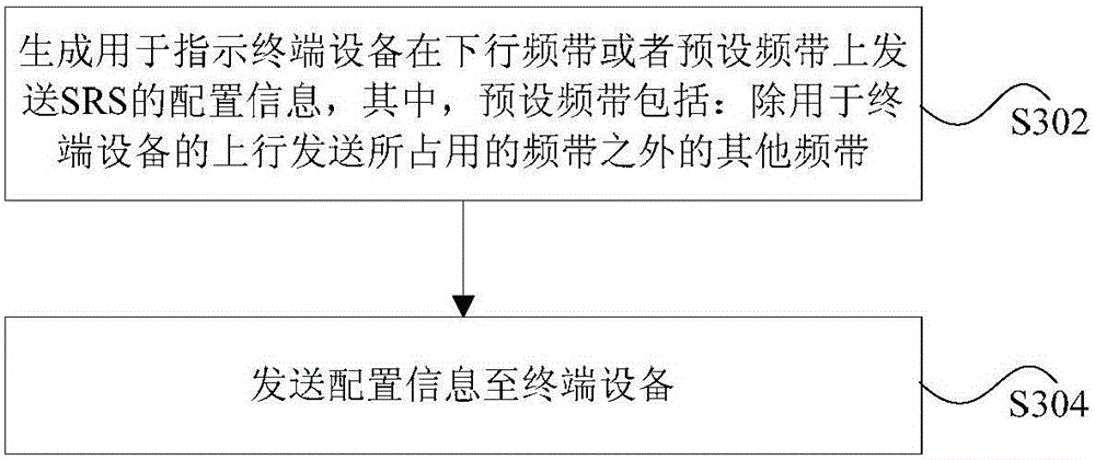
[0139] In this preferred embodiment, the base station sends SRS configuration information to the user terminal, wherein the configuration information includes: information used to instruct the terminal device to send SRS on the downlink frequency band; information used to instruct the terminal device to send SRS on the downlink frequency band information, including: the SRS transmission period configured on the downlink frequency band;

[0140] The base station configures the SRS transmission cycle on the downlink frequency band for the terminal device through high-layer RRC signaling. When the terminal device is in the subframe of the SRS transmission cycle in the downlink frequency band, the terminal device sends the SRS on the subframe; for example, the subframe index When the following formula is satisfied, the SRS is sent on the subframe.

[0141] (10 n f +k SRS -T offset ) modT SRS =0

[0142] Among them, nf is the system frame number, k SRS is the subframe index, ...

Embodiment 2

[0153] In this preferred embodiment, the base station sends SRS configuration information to the user terminal, wherein the configuration information includes: information used to instruct the terminal device to send SRS on the downlink frequency band; information used to instruct the terminal device to send SRS on the downlink frequency band information, including: the SRS transmission period configured on the downlink frequency band;

[0154] Preferably, before setting the SRS configuration information, the base station receives capability information of the terminal device sent by the terminal device, wherein the capability information is used to indicate whether the terminal device has the capability of sending SRS or uplink data on the downlink frequency band.

[0155] When the terminal device has the ability to send uplink SRS on the downlink frequency band and the base station has the ability to receive uplink on the downlink frequency band, the base station can configur...

Embodiment 3

[0158] The method for sending a measurement reference signal provided in this preferred embodiment is realized by a system including a base station and a user terminal (equivalent to the above-mentioned terminal equipment). Wherein, the base station sets the configuration information of the SRS, and sends the configuration information of the SRS to the terminal device; the configuration information includes: information used to instruct the terminal device to send the SRS on the downlink frequency band;

[0159] Preferably, the information used to instruct the terminal device to send the SRS on the downlink frequency band includes: the SRS request field in the downlink control signaling, and the information used to indicate the transmission of the SRS in the downlink control signaling;

[0160] Preferably, the SRS request field in the downlink control signaling includes: when the value of the SRS request field in the downlink control signaling is valid and the communication sys...


PUM


Abstract

The invention provides an SRS instruction transmission method and a SRS transmission method and device. The SRS instruction transmission method comprises generating configuration information instructing a terminal device to transmit an SRS in a downlink frequency band or a preset frequency band, wherein the preset frequency band includes frequency bands except the frequency bands occupied by the uplink transmission of the terminal device; and transmitting the configuration information to the terminal device. The SRS instruction transmission method solves a waste of downlink pilot frequency resource overhead and terminal feedback overhead in a FDD system of Massive MIMO and reduces the downlink pilot frequency resource overhead and the feedback amount of the terminal.

Description

technical field [0001] The present invention relates to the communication field, in particular to a method for sending an SRS indication, a method and a device for sending an SRS. Background technique [0002] The radio frame in the Long Term Evolution (referred to as LTE) system includes frequency division duplex (Frequency Division Duplex, referred to as FDD) mode and time division duplex (Time Division Duplex, referred to as TDD) mode frame structure. figure 1 It is a schematic diagram of the frame structure of the FDD mode according to the related technology, such as figure 1 As shown, a wireless frame of 10 milliseconds (ms) consists of twenty slots (slots) with a length of 0.5ms and numbers 0 to 19, and slots 2i and 2i+1 form a subframe (subframe) with a length of 1ms i. figure 2 is a schematic diagram of a frame structure of a TDD mode according to related technologies, such as figure 2 As shown, a 10ms radio frame consists of two half frames with a length of 5m...

Claims


Application Information

Patent Timeline
Patent Type & Authority Applications(China)
IPC IPC(8): H04B7/0413H04L5/00
CPCH04B7/0413H04L5/0048H04B7/04H04L5/00
Inventor 王瑜新鲁照华陈艺戬李儒岳
Owner ZTE CORP
Why Eureka
Try Eureka