Component Feeder With Flexible Retaining Walls

a technology of flexible retaining walls and components, applied in the field of retaining walls, can solve problems such as compromising efficacy, and achieve the effects of reducing the footprint, improving the resistance to component escape, and being convenient to deform

Active Publication Date: 2015-08-20
ABB (SCHWEIZ) AG
View PDF4 Cites 1 Cited by
  • Summary
  • Abstract
  • Description
  • Claims
  • Application Information

AI Technical Summary

Benefits of technology

[0003]One object of the invention is to provide an improved component feeder wherein components can be picked close to a retaining wall without compromising the resistance against component escape.
[0007]According to one embodiment of the invention, the retaining wall comprises material having Young's modulus value less than 50 MPa, such as less than 20 MPa, such as less than 10 MPa, such as less than 5 MPa, such as less than 2 MPa, or such as less than 1 MPa. The flexibility of the retaining wall can be easily achieved by manufacturing the retaining wall from an appropriate material.
[0009]According to one embodiment of the invention, the retaining wall has in the direction of its height a stiffness less than 100 N / mm, such as less than 10 N / mm, such as less than 5 N / mm, such as less than 2 N / mm, or such as less than 1 N / mm. When the stiffness of the retaining wall has a certain relatively low value in the direction of its height, a robot gripper approaching from above can easily deform the retaining wall in this direction.
[0010]According to one embodiment of the invention, the retaining wall has a height of at least five times the thickness, such as at least ten times the thickness, such as at least twenty times the thickness, or such as at least thirty times the thickness. A relatively high and thin retaining wall is easily deformable. A higher retaining wall provides a better resistance against component escape, and a thinner retaining wall provides a smaller footprint around the pick surface.
[0011]According to one embodiment of the invention, the retaining wall is vertical. A vertical retaining wall renders the footprint of the same around the pick surface as small as possible.

Problems solved by technology

The retaining wall 40 can be made lower, but this compromises its efficacy.

Method used


Image

  • Component Feeder With Flexible Retaining Walls
  • Component Feeder With Flexible Retaining Walls
  • Component Feeder With Flexible Retaining Walls

Examples


Embodiment Construction

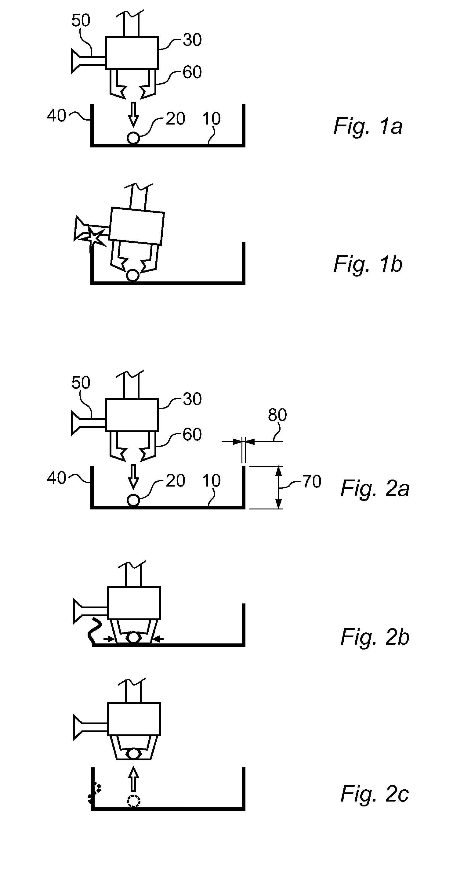
[0017]Referring to FIG. 2, a pick surface 10 surrounded by a flexible retaining wall 40 is shown. The suction tool 50 of the robot gripper 30 collides with the retaining wall 40 causing the same to deform. Consequently, the retaining wall 40 does not impede the robot gripper fingers 60 access to the component 20. Once the component 20 has been picked, the retaining wall 40 assumes its original shape. The height 70 of the retaining wall is five to thirty times the thickness 80 of the same.

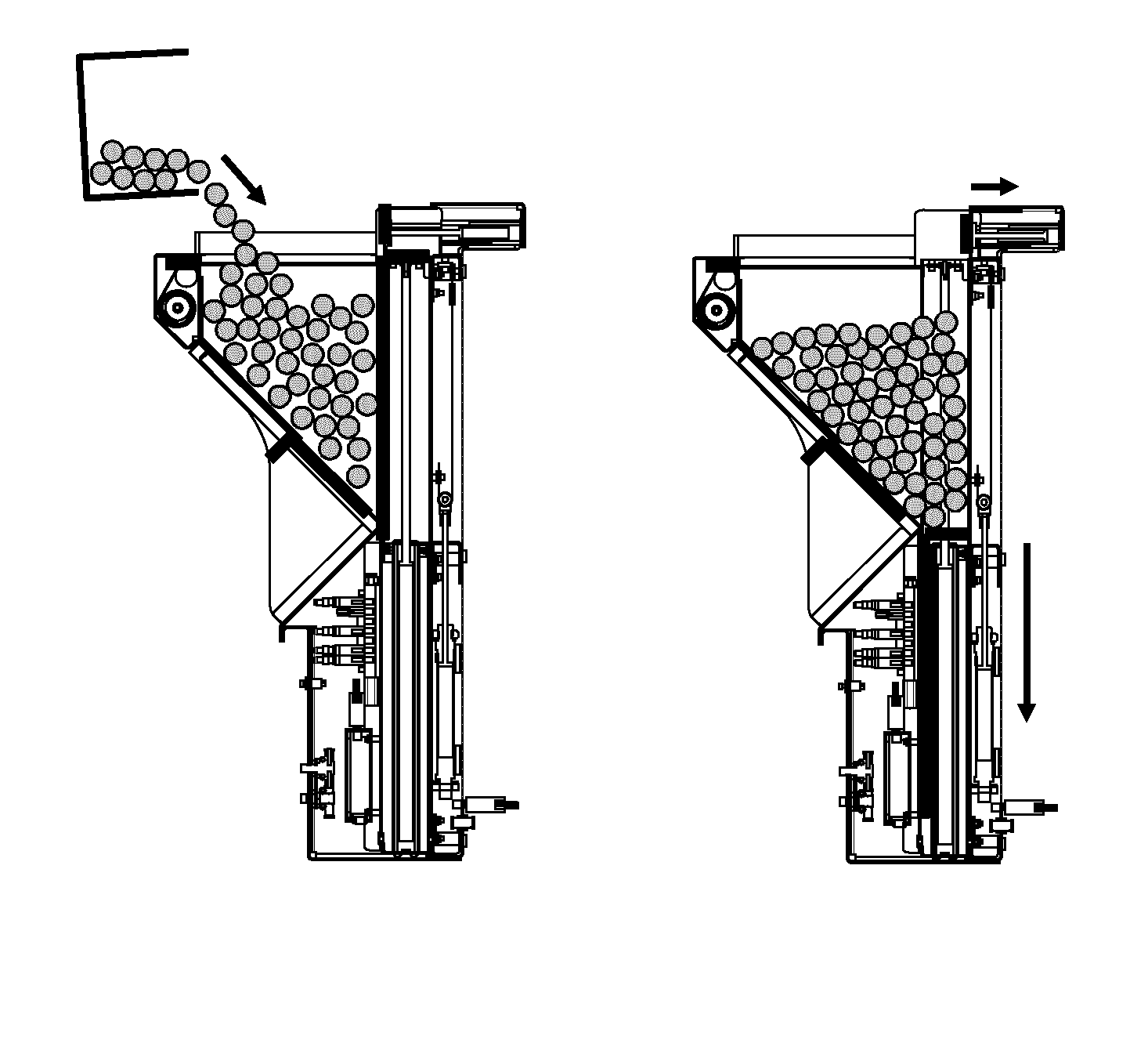
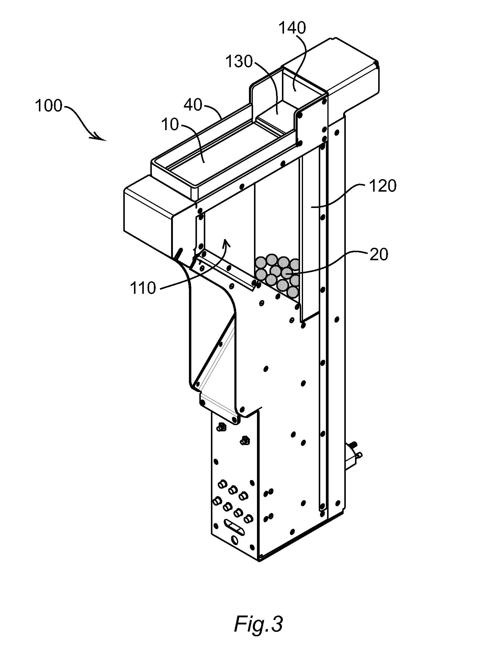
[0018]Referring to FIG. 3, one embodiment of a component feeder 100 according to the invention comprises a triangular hopper 110 for receiving a bulk storage of components 20 to be fed. At the rear of the hopper 110 there is provided a vertically acting lift 120 with a horizontal lift platform 130 for lifting the components 20. In the upper rear corner of the component feeder 100 there is provided a horizontally acting spreader in the form of a pusher plate 140. A retractable pick surface 10 covers ...


PUM


Abstract

A component feeder includes a distributer for distributing components from a bulk storage on a pick surface, and a retaining wall preventing the components from escaping the pick surface. The retaining wall is flexible such that it deforms when a force is applied on it, and it assumes its original shape when the force is no longer applied. The flexible retaining wall allows a robot gripper to push the retaining wall aside when picking a component close to the retaining wall.

Description

FIELD OF THE INVENTION[0001]The present invention relates to a retaining wall preventing components from escaping a pick surface of a component feeder.BACKGROUND OF THE INVENTION[0002]Referring to FIG. 1a, a conventional component feeder comprises a pick surface 10 on which components 20 are distributed, and from which the components 20 are subsequently picked e.g. by means of a robot gripper 30. A pick surface 10 is typically a planar and horizontal surface which is surrounded by a retaining wall 40 for preventing the components 20 from escaping the pick surface 10. It is desirable to have a high retaining wall 40 for maximum resistance against component escape. A high retaining wall 40, however, poses a problem when components 20 near the retaining wall 40 should be picked since part of the robot gripper 30, such as a suction tool 50, may collide with the retaining wall 40 before the robot gripper fingers 60 can reach the component 20, as illustrated in FIG. 1b. The retaining wall...

Claims


Application Information

Patent Timeline
Patent Type & Authority Applications(United States)
IPC IPC(8): B65D83/04B65G65/00
CPCB65D83/04B65G2201/02B65G65/00B65G47/1471B65G47/91H05K13/028
Inventor SIRKETT, DANIELNYLEN, PERLUNDBERG, IVAN
Owner ABB (SCHWEIZ) AG
Why Eureka
Try Eureka