Bus bar module

a technology of bus bar and module, which is applied in the field of bus bar module, can solve the problems of deformation or damage of the electrical components of the battery cell, and achieve the effects of reducing load, increasing clearance, and reducing load

Active Publication Date: 2015-10-13
YAZAKI CORP
View PDF6 Cites 0 Cited by
  • Summary
  • Abstract
  • Description
  • Claims
  • Application Information

AI Technical Summary

Benefits of technology

[0012]The invention has been implemented in order to solve the conventional problem as described above, and an object of the invention is to provide a bus bar module capable of preventing an electrode of an assembled battery from being deformed or damaged by a load from above without increasing installation space.
[0021]By this construction, when the joining member is subjected to a load from above, while maintaining the arch shape by the rigid part, the load is reduced by bending in the flexible part and the load can be prevented from being transmitted to the first holding member and the second holding member. Also, since the flexible part bends and the load can be reduced, it is unnecessary to increase a clearance between the joining member and a member of the upper part of the joining member, so that an increase in installation space can be prevented.
[0022]Consequently, an electrode of the assembled battery can be prevented from being deformed or damaged by the load from above without increasing the installation space.
[0024]By this construction, the rigid part includes the rib and thereby rigidity can be given to the rigid part and also the flexible part is formed in the flat plate shape by eliminating the rib for rigid maintenance from the flexible part and thereby flexibility can easily be given to the flexible part.
[0026]By this construction, in order to reduce a load in the flexible part arranged on the lower end of the joining member, the flexible part bends vertically and the general arch shape of the joining member can be maintained by the rigid part.

Problems solved by technology

As a result, when the arch-shaped joining member is subjected to a load from an upper portion, this load is transmitted to an electrode or a body of each battery cell of the assembled battery and particularly, the electrode of the battery cell may be deformed or damaged.

Method used


Image

  • Bus bar module
  • Bus bar module
  • Bus bar module

Examples


Embodiment Construction

[0031]An embodiment of a bus bar module according to the invention will hereinafter be described using the drawings.

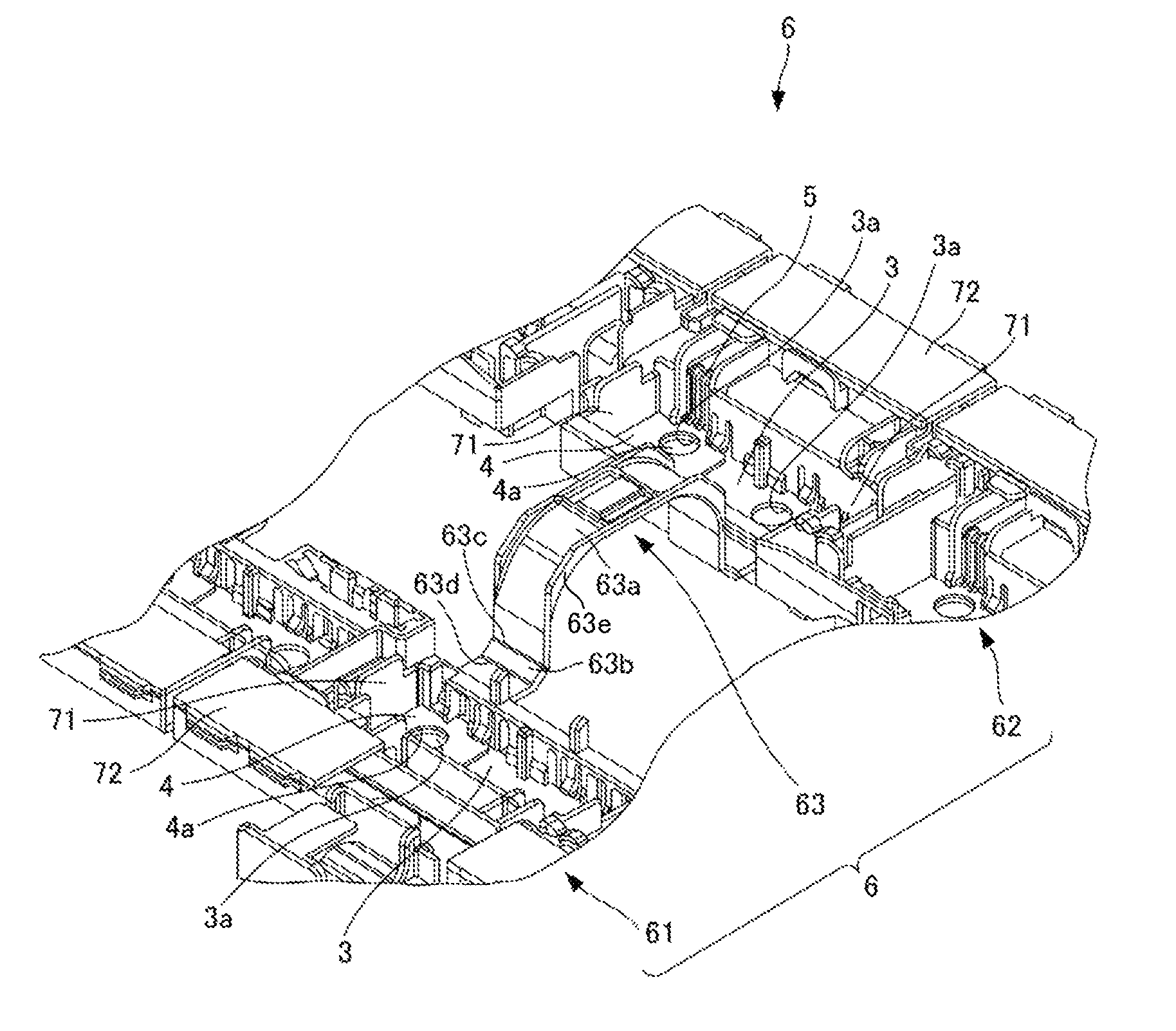
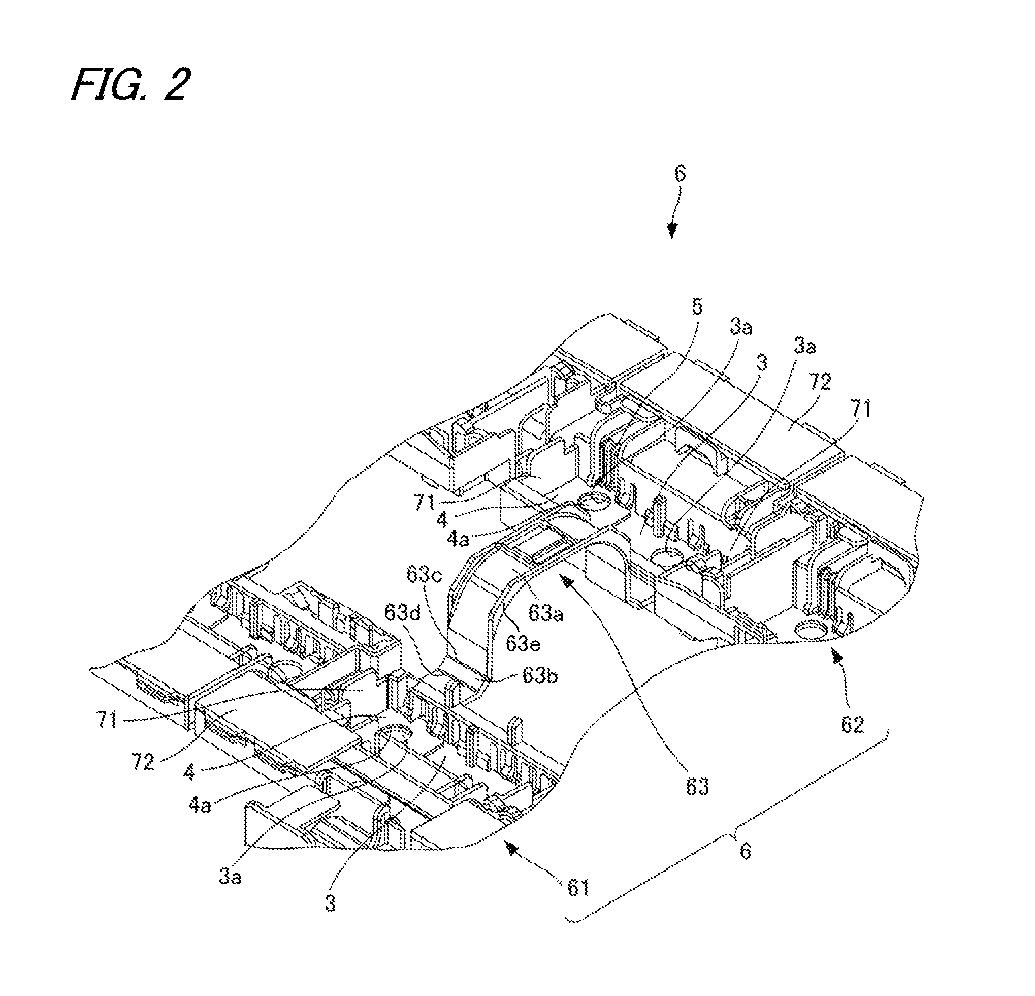
[0032]FIGS. 1 to 3 are views showing one embodiment of the bus bar module according to the invention.

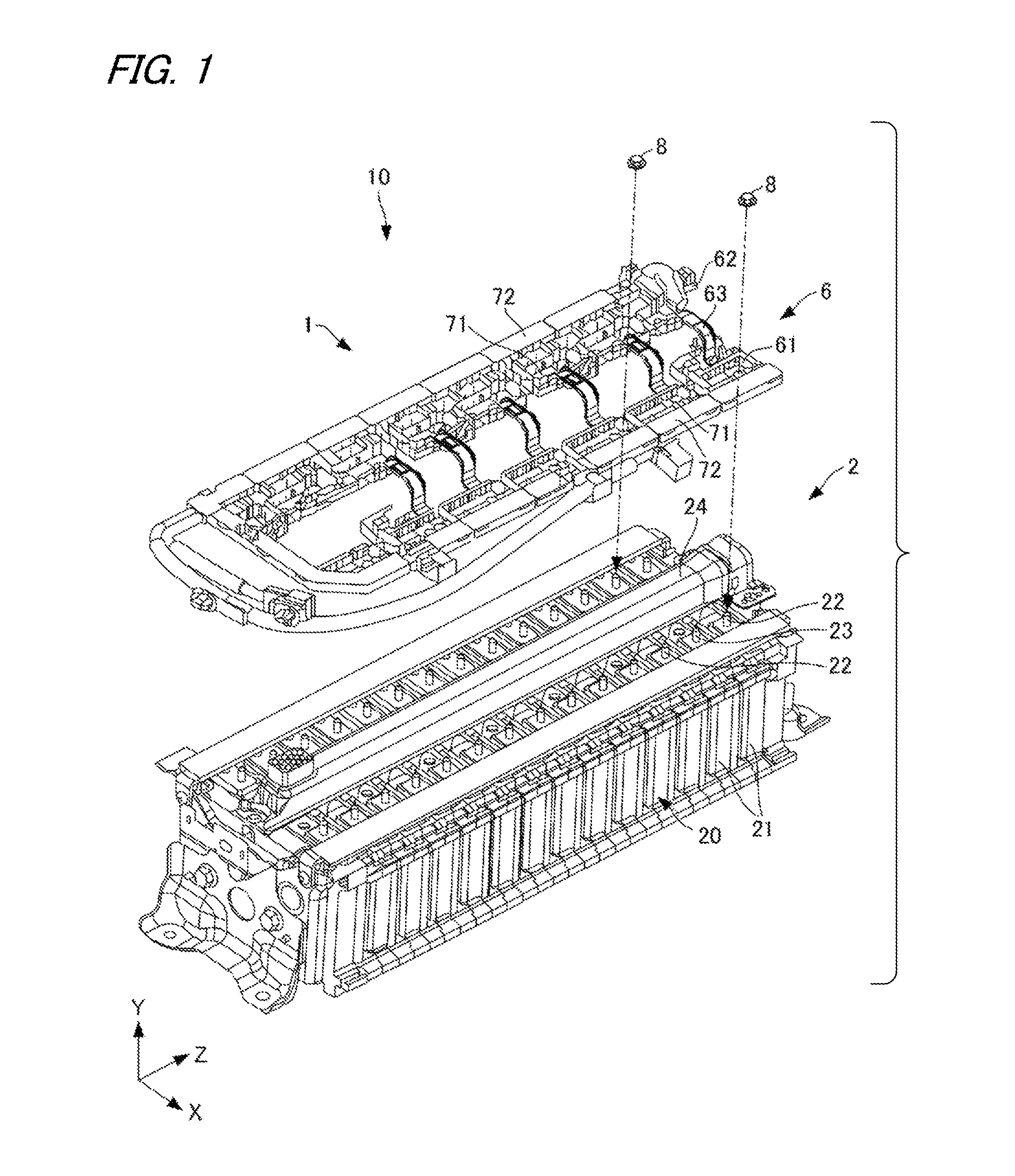
[0033]First, a configuration is described. As shown in FIGS. 1 and 2, a bus bar module 1 of the invention is attached to an assembled battery 2 to construct a power source apparatus 10. The power source apparatus 10 is installed in, for example, an electric vehicle driven using an electric motor as a driving source or a hybrid vehicle driven with a combination of an engine and an electric motor, and supplies electric power to the electric motor.

[0034]In addition, the assembled battery 2 is formed by stacking battery cells (square batteries) having a positive electrode in one end and a negative electrode in the other end alternately in the opposite direction.

[0035]The assembled battery 2 is a battery fixed by mutually stacking plural battery cells 20. Each of the plural ...


PUM

PropertyMeasurementUnit
polaritiesaaaaaaaaaa
mutual distanceaaaaaaaaaa
flexibleaaaaaaaaaa

Abstract

A bus bar module includes a holding member for holding the plural bus bars with a mutual distance between the bus bars maintained. The holding member includes a first holding member for holding the plural bus bars in one electrode line of the plural battery cells, a second holding member for holding the plural bus bars in the other electrode line of the plural battery cells, and a joining member for structurally joining the first holding member to the second holding member. The joining member is formed in an arch shape upwardly projected from inside ends of the first holding member and the second holding member. The joining member has a rigid part adapted to maintain the arch shape and a flexible part adapted to vertically bend by a load from above.

Description

CROSS REFERENCE TO RELATED APPLICATIONS[0001]This application is a continuation of PCT application No. PCT / JP2013 / 052287, which was filed on Jan. 24, 2013 based on Japanese Patent Application (No. 2012 / 012198) filed on Jan. 24, 2012, the contents of which are incorporated herein by reference.BACKGROUND OF THE INVENTION[0002]1. Field of the Invention[0003]The present invention relates to a bus bar module, and particularly to a bus bar module for connecting plural battery cells of an assembled battery in series.[0004]2. Description of the Related Art[0005]As a bus bar module attached to an assembled battery configured by stacking plural battery cells, a bus bar module configured to have plural terminals connected to each electrode of a battery cell, plural electric wires connected to each terminal, a plate and a cover is known conventionally (for example, see PTL 1).[0006]In the bus bar module described in PTL 1, the plate has plural terminal receiving parts and plural electric wire r...

Claims


Application Information

Patent Timeline
Patent Type & Authority Patents(United States)
IPC IPC(8): H02G5/06H01M2/20H01M2/10H02G5/00H01M2/12H01M10/0525H01M50/209H01M50/358H01M50/507H01M50/51
CPCH02G5/00H01M2/1077H01M2/206Y02T10/7011H01M10/0525H01M2220/20H01M2/1252H01M50/51H01M50/358H01M50/507H01M50/209Y02E60/10Y02T10/70
Inventor ISHIKAWA, MASAHIROOGASAWARA, SHIGEYUKISYOUJI, TAKAO
Owner YAZAKI CORP
Why Eureka
Try Eureka