
Connector and housing thereof

a technology of connecting rods and housings, which is applied in the direction of coupling device connections, coupling protective earth/shielding arrangements, two-part coupling devices, etc., can solve the problems of additional replacement trouble, long and more complicated process of soldering, and increased manufacturing cost of connectors, so as to reduce the manufacturing process and reduce the manufacturing time , direct disassembly

Inactive Publication Date: 2008-06-12
DELTA ELECTRONICS INC
View PDF4 Cites 4 Cited by
  • Summary
  • Abstract
  • Description
  • Claims
  • Application Information

AI Technical Summary

Benefits of technology

[0009]In view of the foregoing, the present invention is to provide a connector, which is manufactured without a soldering process and has lower cost, and a housing thereof.
[0012]As mentioned above, a ground element is formed on the body of the housing of a connector of the present invention. The ground element of the housing is disposed with respect to the PCB and is electrically connected with the ground end of the PCB by clipping or hooking, so that no soldering is involved. In comparison with the prior art, the present invention has a direct contact between the ground element of the housing and the PCB, so that the soldering process and related equipments are not necessary. Therefore, the manufacturing process is simplified and the production time is shortened. Moreover, the ground element of the present invention can be formed just by bending a part of the body of the housing. When the PCB is assembled into the housing of the connector, it only needs to have one simply touch between the body of the housing and the ground element of the PCB, there is no soldering process to be performed. Also, once the PCB is damaged and needs to be replaced, it can be directly disassembled without difficulty so as to have advantages of easy replacing and flexibility.

Problems solved by technology

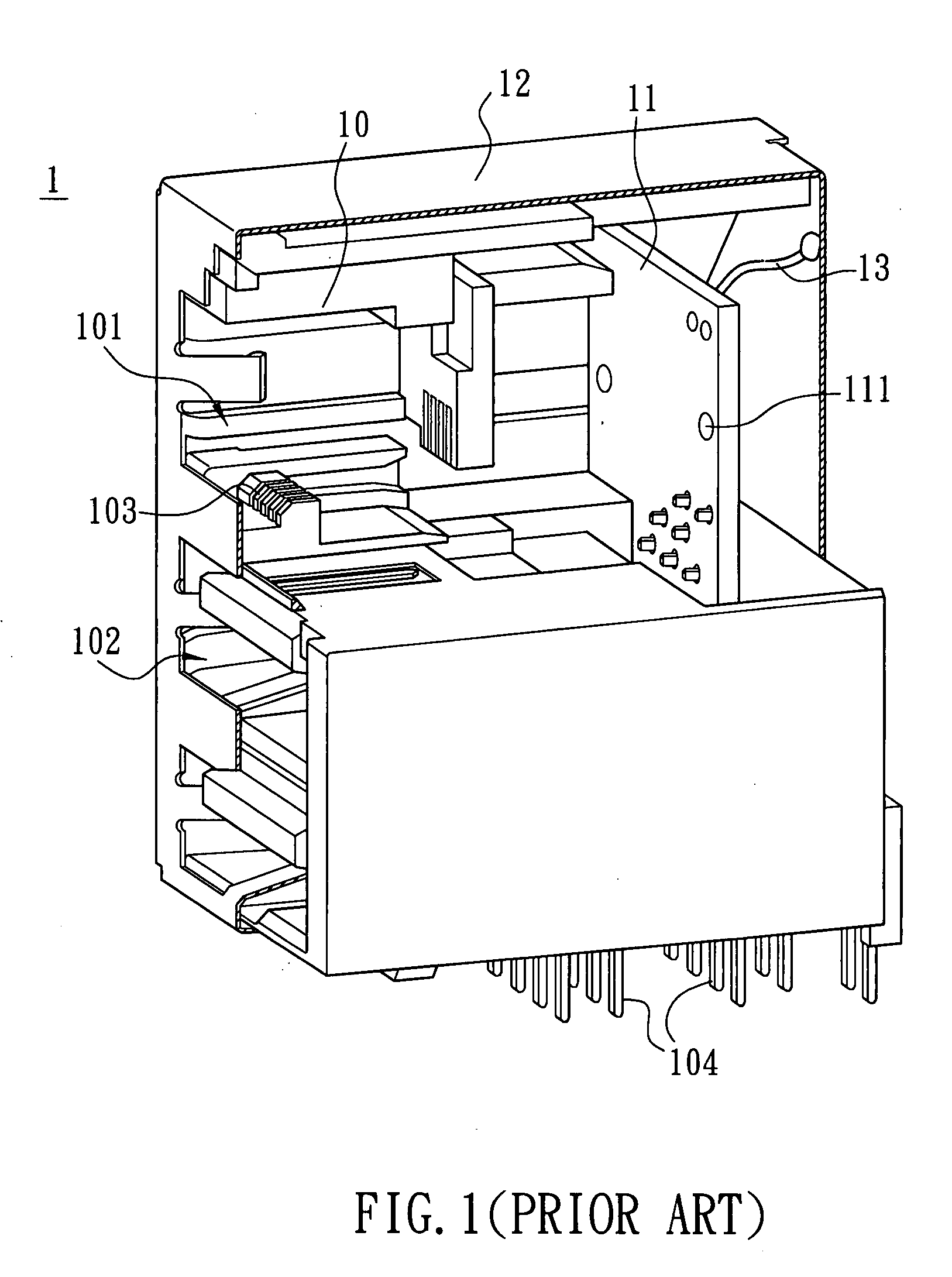
However, this method of using a ground wire 13 not only adds an additional component to the connector but also involves a longer and more complicated process due to soldering.
Therefore, the manufacturing cost of the connector is inevitably higher.
Also, once the PCB is damaged and needs to be replaced, the ground wire 13, being soldered onto the metal housing, causes additional troubles for replacement.

Method used


Image

  • Connector and housing thereof
  • Connector and housing thereof
  • Connector and housing thereof

Examples


Embodiment Construction

[0018]The present invention will be apparent from the following detailed description, which proceeds with reference to the accompanying drawings, wherein the same references relate to the same elements.

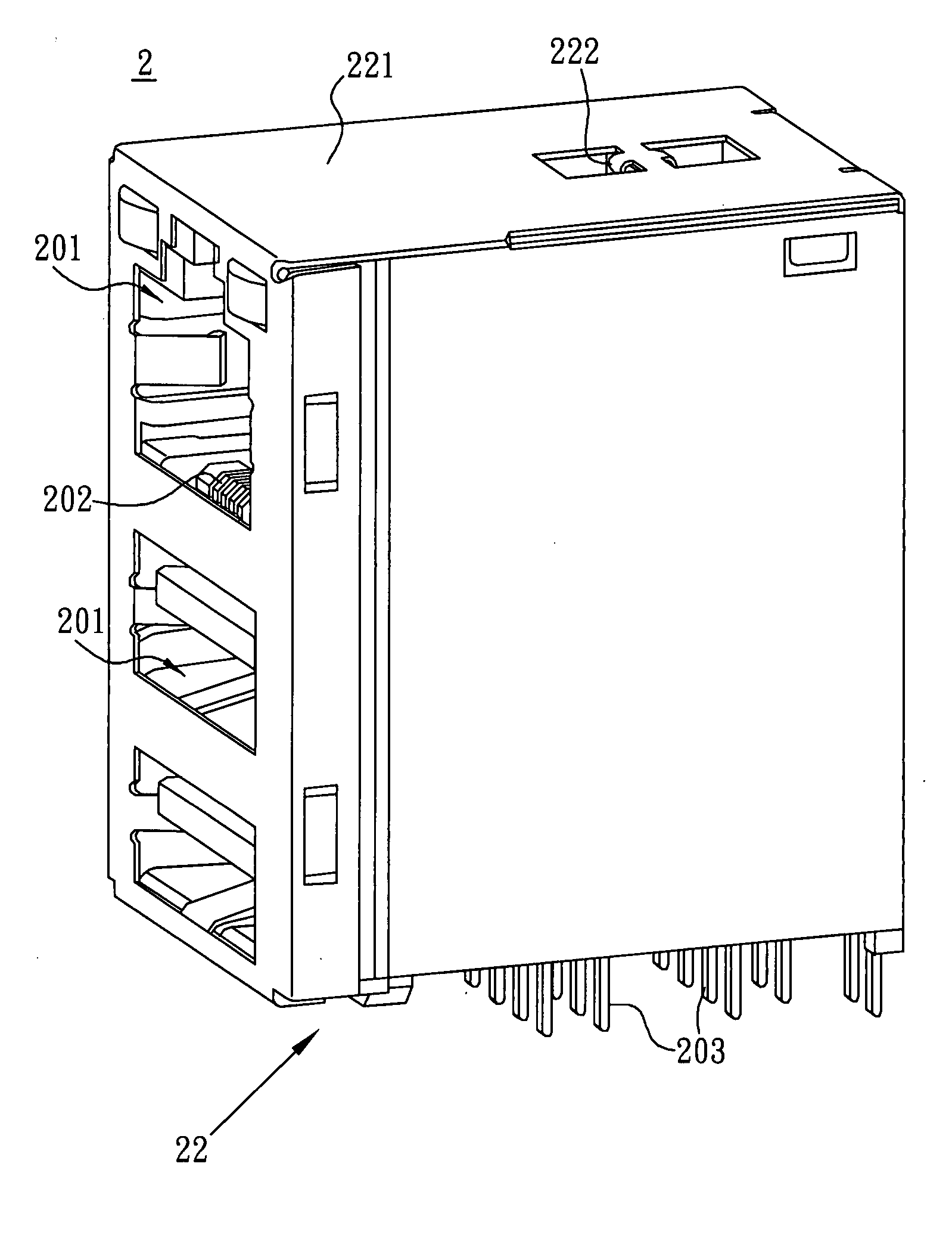
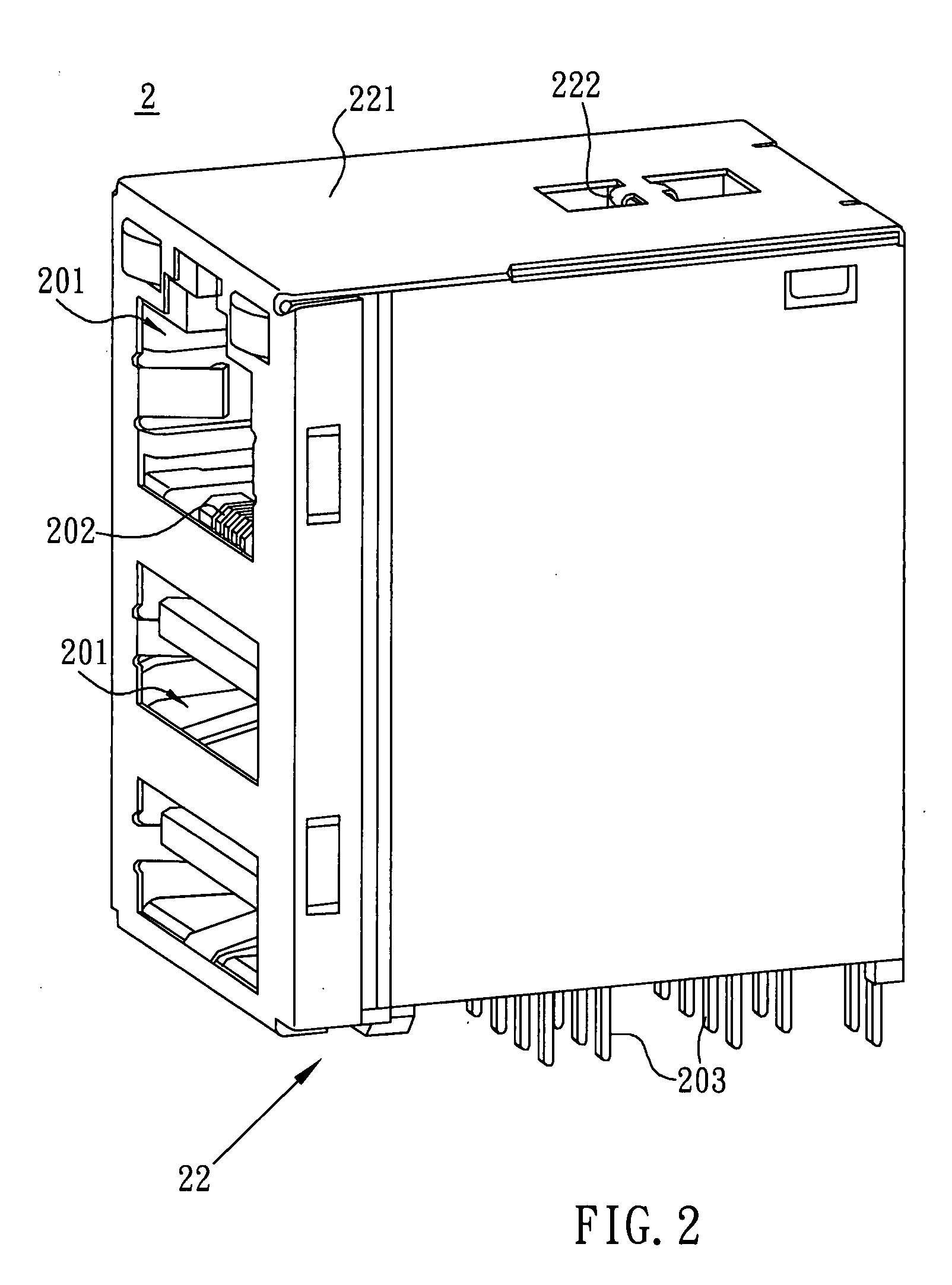
[0019]Referring both to FIGS. 2 and 3. According to an embodiment of the present invention, a connector 2 includes a connecting base 20, a circuit board 21, such as a printed circuit board (PCB), and a housing 22.

[0020]The connecting base 20 has at least one container 201 with several terminals 202 embedded therein. The container 201 is a connecting hole satisfying the RJ-11, RJ-12, RJ-45, or USB specification. The connecting base 20 may have several containers 201, with some combination of the RJ-11, RJ-12, RJ-45, and USB connecting holes. The connector 2 in this embodiment has an RJ-45 connecting hole and two USB connecting holes.

[0021]The connecting base 20 further has several pins 203. The terminals 202 are electrically connected to corresponding pins 20 via the PCB 21 in order to...


PUM


Abstract

A connector includes a circuit board and a housing. The housing has a body and a ground element, wherein the ground element is connected with the body and is disposed with respect to the circuit board. The ground element is in electrical contact with a ground end of the circuit board by clipping or hooking. The ground element and the body are integrally formed as a single piece, and the ground element is elastically deformable.

Description

CROSS REFERENCE TO RELATED APPLICATIONS[0001]This Non-provisional application claims priority under 35 U.S.C. §119(a) on Patent Application No(s). 095145993, filed in Taiwan, Republic of China on Dec. 8, 2006, the entire contents of which are hereby incorporated by reference.BACKGROUND OF THE INVENTION[0002]1. Field of Invention[0003]The present invention relates to a connector and the housing thereof. In particular, it relates to a connector and its housing without grounding by soldering.[0004]2. Related Art[0005]With rapid development in information technology, computers have become very popular. By using the network technology, people can quickly obtain the required information from the Internet or provide various information services to others. Therefore, it has become a trend of the information era to connect computers or peripheral devices to the network.[0006]In general, people use a connector to connect the network with related electronic devices. As shown in FIG. 1, a conve...

Claims


Application Information

Patent Timeline
IPC IPC(8): H01R13/648
CPCH01R13/65802H01R24/62H01R27/02H01R13/6658H01R13/6582
Inventor TAI, YU-YUANGUAN, ZHAO-WEIZUO, YUN
Owner DELTA ELECTRONICS INC
Learn More