Method and circuit for evaluating a physical quantity detected by a sensor

a physical quantity and sensor technology, applied in the field of sensors, can solve the problems of temperature dependence of the evaluation signal, eddy current, increase of the attenuation of the oscillator, etc., and achieve the effect of reducing power consumption and reducing the number of components

Active Publication Date: 2015-08-20
PEPPERL FUCHS GMBH
View PDF3 Cites 2 Cited by
  • Summary
  • Abstract
  • Description
  • Claims
  • Application Information

AI Technical Summary

Benefits of technology

[0012]It is an object of the present invention to provide a method and a circuit for evaluating a physical quantity detected by a sensor element which can supply a sensor output as an electrical direct (DC) quantity which is based on an electrical oscil

Problems solved by technology

This results in eddy currents in the body which themselves generate an interfering magnetic field which overlays the alternating magnetic field.
A change of impedance imposed by the interfering magnetic field or an interference of an alternating magnetic field can result in an increase of the attenuation in the oscillator.
The use of diode circuits or active rectifier

Method used


Image

  • Method and circuit for evaluating a physical quantity detected by a sensor
  • Method and circuit for evaluating a physical quantity detected by a sensor
  • Method and circuit for evaluating a physical quantity detected by a sensor

Examples


Embodiment Construction

[0047]Example embodiments will now be described more fully with reference to the accompanying drawings.

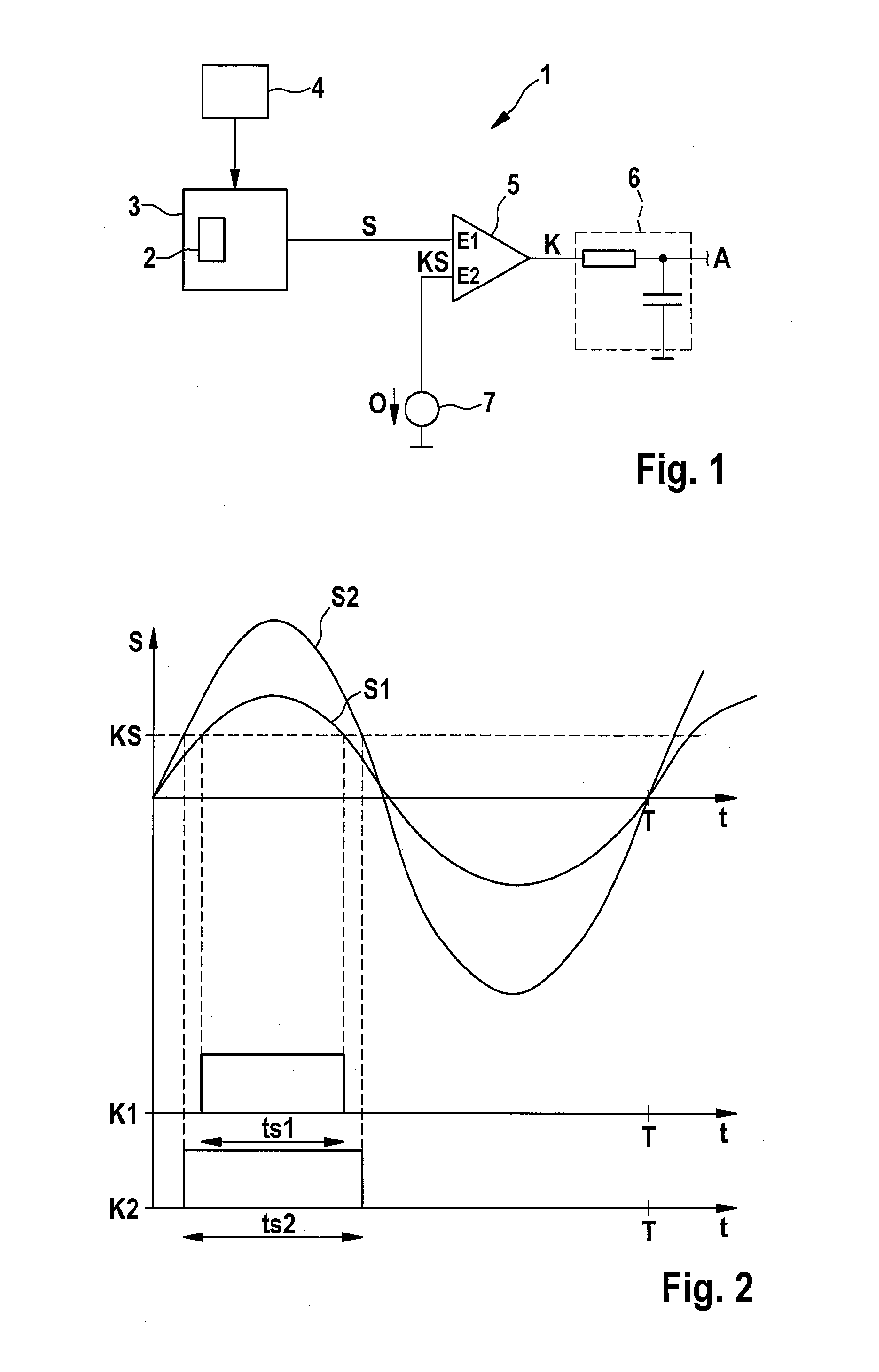
[0048]FIG. 1 schematically shows an evaluating circuit 1 for a sensor element 2 which is part of a resonant circuit 3 or oscillator, respectively. The sensor element 2 serves to measure a physical quantity and to have a function within the resonant circuit 3 so that a periodic oscillation signal is generated with an amplitude depending on the physical quantity to be measured. For instance, the sensor element 2 can be chosen so that a change of the physical quantity to be measured results in a change of impedance of the sensor element 2. The variation of impedance results in a varying attenuation of the periodic oscillation signal which can be evaluated.

[0049]The resonant circuit 3 is continuously excited by means of an excitation means 4 to provide the periodic oscillation signal S. The excitation means 4 serves on one hand to effect an initial build-up of oscillation of the resona...


PUM


Abstract

A method for measuring a physical quantity with a, particularly inductive, sensor element and for providing a sensor output depending on the physical quantity. The sensor element is part of a resonant circuit whose attenuation depends on the physical quantity being measured. The resonant circuit is excited to generate a periodic oscillation signal, the amplitude of which depends on the attenuation. The oscillation signal is compared with a comparator threshold value in a comparator to produce a periodic comparator signal with a duty cycle depending on the comparator threshold value. The comparator threshold value is set to be different from a mean value of the oscillation signal so that a duty cycle different from 50% is achieved. The sensor output is output depending on the duty cycle of the comparator signal.

Description

CROSS-REFERENCE TO RELATED APPLICATIONS[0001]This application claims the benefit and priority of European Patent Application No. 14155957.5 filed on Feb. 20, 2014, the entire disclosure of which is incorporated by reference herein.BACKGROUND[0002]This section provides background information related to the present disclosure which is not necessarily prior art.TECHNICAL FIELD[0003]The present invention generally relates to sensors, particularly sensors for use in an oscillator, wherein an oscillation signal depending on a physical quantity is provided. Furthermore, the present invention relates to possibilities for evaluating an oscillating signal influenced by a sensor element to obtain a sensor output.DISCUSSION[0004]Inductive and capacitive sensor elements are often used in sensor appliances with contactless sensing. Electrical characteristics of inductive or capacitive sensor elements may change depending on a physical quantity to be measured and are usually evaluated by means of ...

Claims


Application Information

Patent Timeline
IPC IPC(8): G01N27/02
CPCH03K17/9512H03K17/954H03K17/9542G01N27/025
Inventor SEEFRIED, ROLAND
Owner PEPPERL FUCHS GMBH
Why Eureka
Try Eureka