Multiple coil flux pad

a flux pad and coil technology, applied in the direction of electric vehicle charging technology, inductance, transportation and packaging, etc., can solve the problems of increasing the magnetic field leakage present in the system, no power transfer possibility, and mismatch between charging and pickup pads

Inactive Publication Date: 2015-08-20
AUCKLAND UNISERVICES LTD
View PDF20 Cites 78 Cited by
  • Summary
  • Abstract
  • Description
  • Claims
  • Application Information

AI Technical Summary

Benefits of technology

[0038]According to one embodiment, the ferrite material extends beyond the extent of the coils. Preferably the increased extent of the provision of ferrites is provided at edges of the coils that cross the imaginary line (or are proximate thereto) but that are at the outer extremities of the coil / ferrite arrangement. Elsewhere, the coils may extend beyond the extent of the ferrites. Such arrangements of the ferrites and coils can improve efficiency and reduce the amount of ferrite material required because it is believed that only ferrite provided substantially along the imaginary lines will add to mutual inductance, ferrite material elsewhere simply adding to inductance. Extending the ferrite material beyond the extent of the coils along the imaginary lines can serve to capture flux spill out or over. This aspect of the invention may comprise only two coils and is not to be limited as requiring three or more coils.
[0046]Providing currents with different phases in each coil and adjusting the overlap between the coils, enables each coil to be substantially decoupled from all other coils.
[0055]Thus, the present invention provides all of the flexibility and functionality described in WO 2011 / 16737 but provides additional functionality and flexibility by enabling additional single coils or pairs of coils that may be energised, as well as enabling higher numbers of coils to be energised, thereby enabling the flux to be better tailored and improve power transfer. For example, the coils energised may be selected at least in part on the required rate of power transfer or the relative position between the pickup and the charging pad.
[0063]Preferably the absence of mutual coupling is detected by detecting when an open circuit voltage induced in a first one of the coils by energisation of at least one (but preferably all) of the other coils is minimised.

Problems solved by technology

A further problem to be solved is the need to be able to couple to vehicles or appliances with varying ground clearances, which largely determines the distance between the charging pad on the ground or as part of a primary structure (such as a mat or other surface) and the secondary pad of a particular vehicle or other device.
This operation will also increase the magnetic field leakage present in the system, which may exceed allowable limits defined by regulations.
A further problem may occur if the primary and secondary inductive pads are polarised but oriented at an angle of 90 degrees to each other such that there is no coupling, and thus no possibility of power transfer.
Yet a further problem arises due to the many different possible pad designs and operation methods, and the potential mismatch between the charging and pickup pads.
Under such conditions the ability of a fixed magnetic structure to capture power is limited.

Method used


Image

  • Multiple coil flux pad
  • Multiple coil flux pad
  • Multiple coil flux pad

Examples


Embodiment Construction

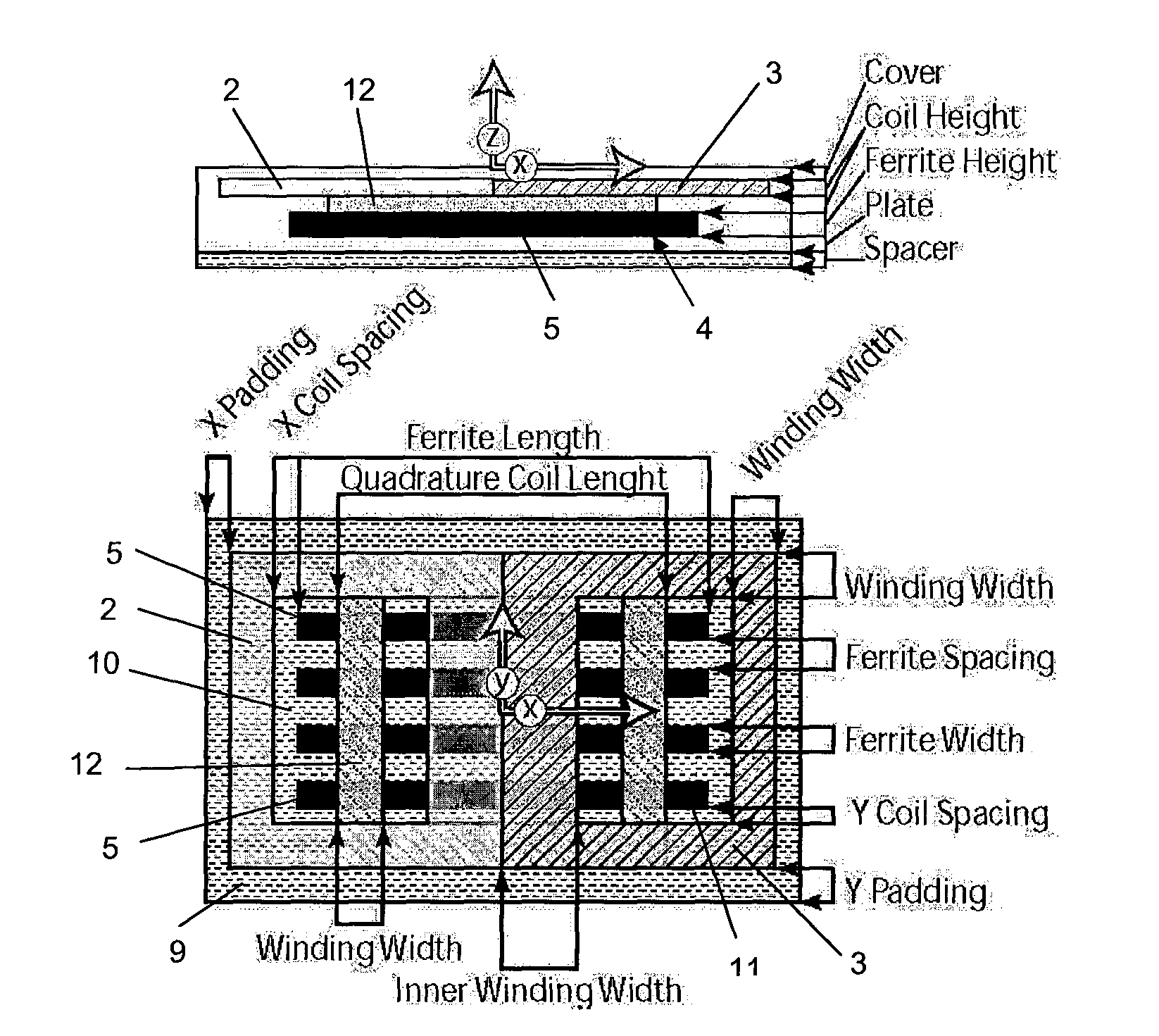
[0116]FIGS. 1 to 3 are prior art arrangements taken from the aforementioned International Patent Publication No. WO 2011 / 16737.

[0117]Referring to FIG. 1, a prior art magnetic flux pad construction is shown. For convenience, this general construction is referred to herein as a DDP pad, and is generally referenced DDP in the relevant drawing figures.

[0118]The DDP pad shown in FIG. 1 generally comprises two substantially coplanar coils referenced 2 and 3 which are magnetically associated with, and sit on top of, a core 4. As can be seen, the core 4 may consist of a plurality of individual lengths of permeable material such as ferrite strips or bars 5 which are arranged parallel to each other but spaced apart. The pad construction may include a spacer 6 on which the core is located, and a plate 7 below the spacer. A cover 8 may be provided on the other surface of the flat coils 2 and 3. Padding 9 may be provided about the periphery of the pad. As can be seen, the coils 2 and 3 each defi...


PUM


Abstract

The present invention provides a magnetic flux pad for generating or receiving magnetic flux, comprising at least three coils positioned such that the windings thereof are in substantially the same plane, and a power supply or pickup controller operable to selectively energise or receive power from two or more of the coils such that a magnetic field is produced or received by at least one of a plurality of pairs of the at least three coils. In preferred embodiments, the three or more coils are substantially mutually decoupled, overlapping, and / or equidistantly spaced from one another.

Description

FIELD OF THE INVENTION[0001]This invention relates to apparatus for generating or receiving magnetic flux. The invention has particular, but not sole, application to a low profile, substantially flat device such as a pad for power transfer using an inductive power transfer (IPT) system.BACKGROUND[0002]IPT systems, and the use of a pad which includes one or more windings which may comprise the primary or secondary windings for inductive power transfer, are reproduced in our International Patent Publication No. WO 2008 / 14033, the contents of which are incorporated herein by reference.[0003]One particular example application of IPT power transfer pads is electric vehicle charging, and that application is discussed in this section to provide the background to one application of the invention. However, electric vehicle charging is an example of only one application, and the invention has application to inductive power transfer in general. Electric vehicle charging may occur while the veh...

Claims


Application Information

Patent Timeline
Patent Type & Authority Applications(United States)
IPC IPC(8): H02J5/00
CPCH02J5/005H02J7/025H01F27/2871H01F38/14H02J7/0044H02J2310/48Y02T10/70Y02T10/7072Y02T90/14Y02T90/12H02J50/70H02J50/90H02J50/12H02J50/40H02J50/005H02J50/10H01F27/288
Inventor COVIC, GRANT ANTHONYBOYS, JOHN TALBOT
Owner AUCKLAND UNISERVICES LTD
Why Eureka
Try Eureka