Moving body guide mechanism of machine tool

a machine tool and moving body technology, applied in the direction of feeding apparatus, metal-working machine components, manufacturing tools, etc., can solve the problems of increasing the residual vibration, increasing the size of the spindle guide mechanism, and difficulty in increasing acceleration

Active Publication Date: 2015-08-27
DMG MORI CO LTD
View PDF14 Cites 4 Cited by
  • Summary
  • Abstract
  • Description
  • Claims
  • Application Information

AI Technical Summary

Benefits of technology

[0011]The preferred disclosed embodiments of the present invention have been developed in view of the above-mentioned and / or other problems in the related art. The preferred disclosed embodiments of the present invention can significantly improve upon existing methods and / or apparatuses.

Problems solved by technology

Therefore, there is caused a problem that the spindle guide mechanism is increased in size.
Further, when the ball screw is disposed apart from the axis of the spindle, the ball screw far from the axis of the spindle is driven, which increases the residual vibration and makes it difficult to increase acceleration.
Therefore, there is also a problem that speeding up cannot be achieved.

Method used


Image

  • Moving body guide mechanism of machine tool
  • Moving body guide mechanism of machine tool
  • Moving body guide mechanism of machine tool

Examples


Embodiment Construction

[0031]The preferred disclosed embodiments of the present disclosure are shown by way of example, and not limitation, in the accompanying figures.

[0032]Hereinafter, there will be explained an embodiment of the present disclosure based on the attached drawings.

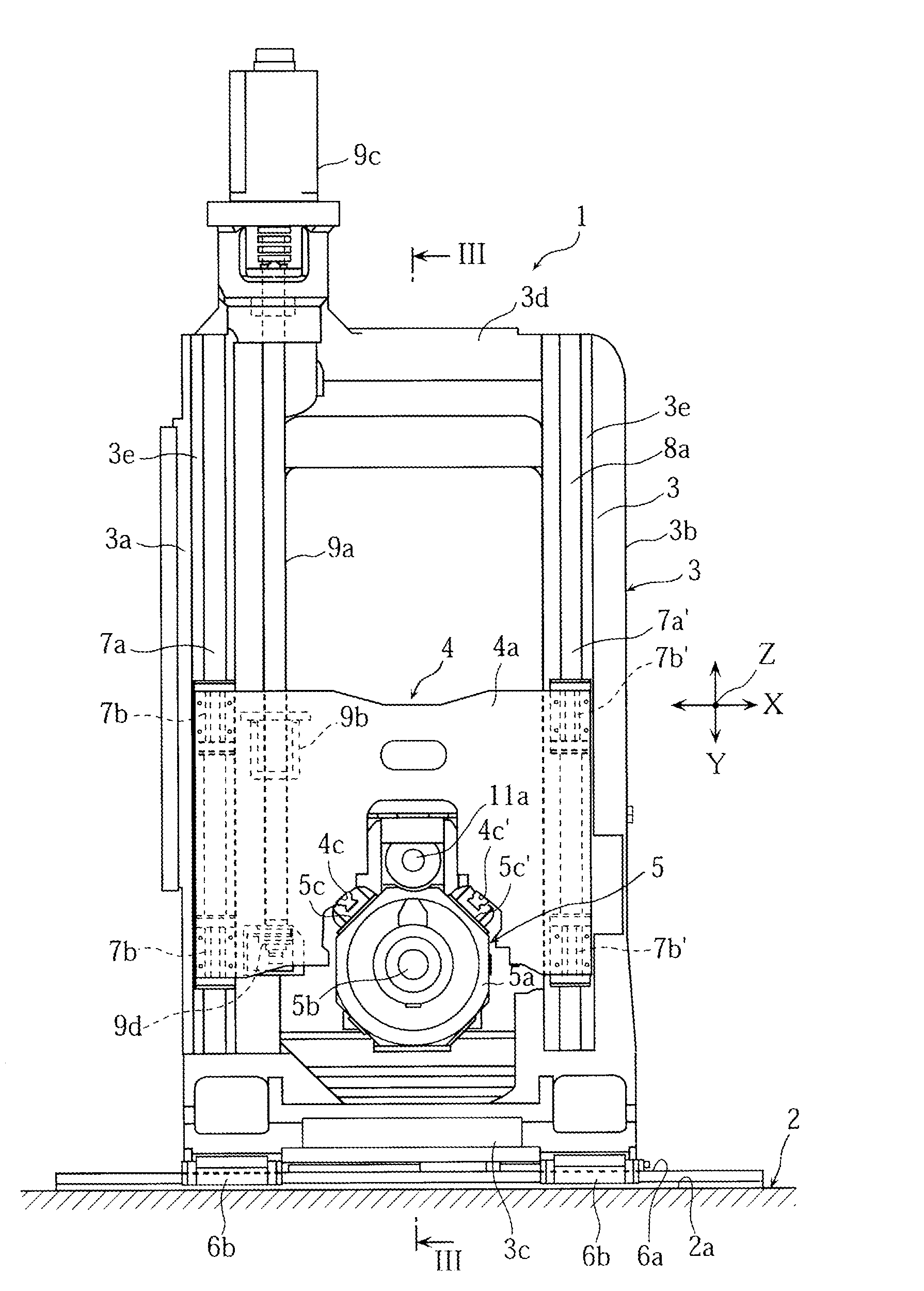
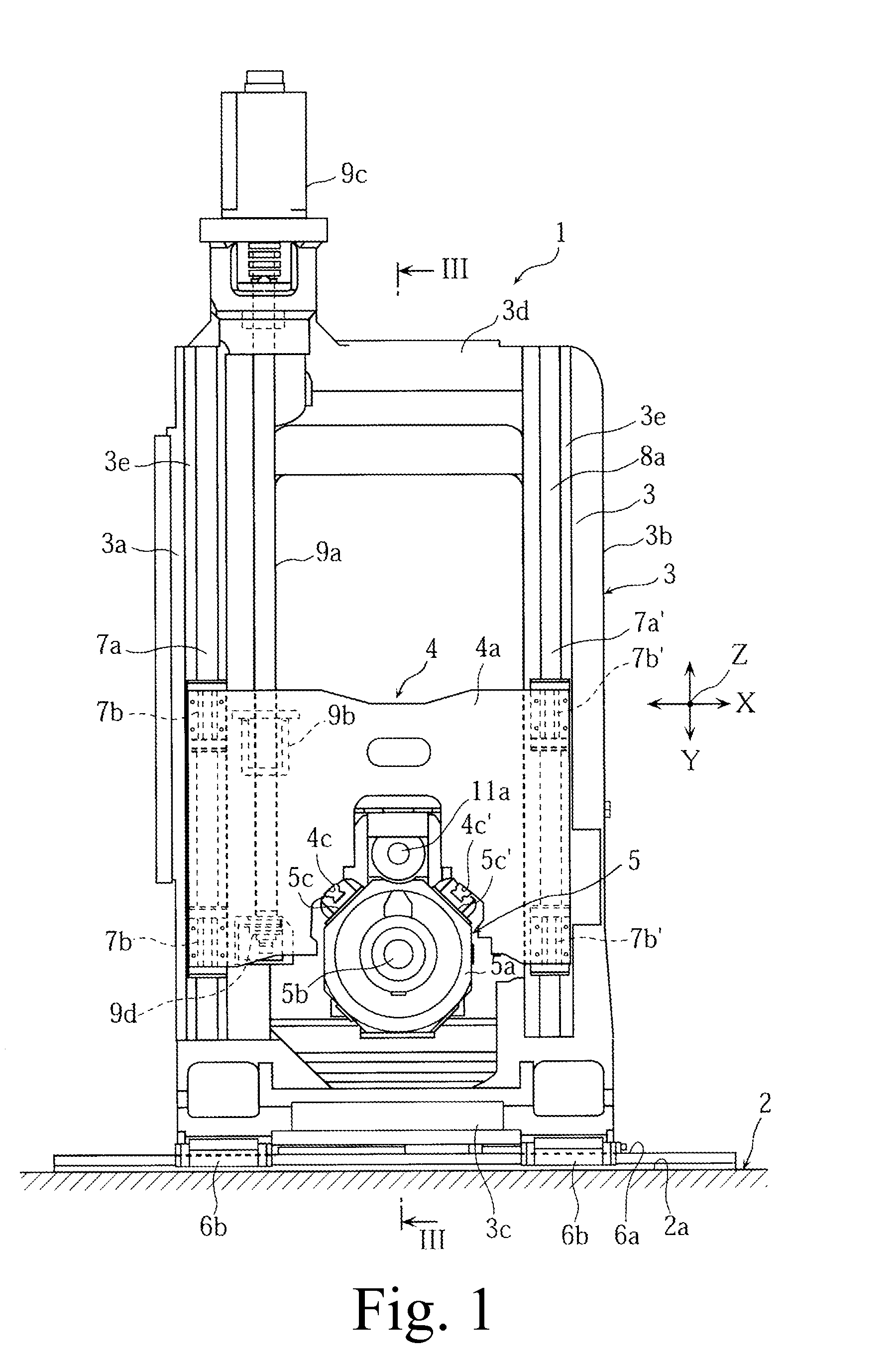
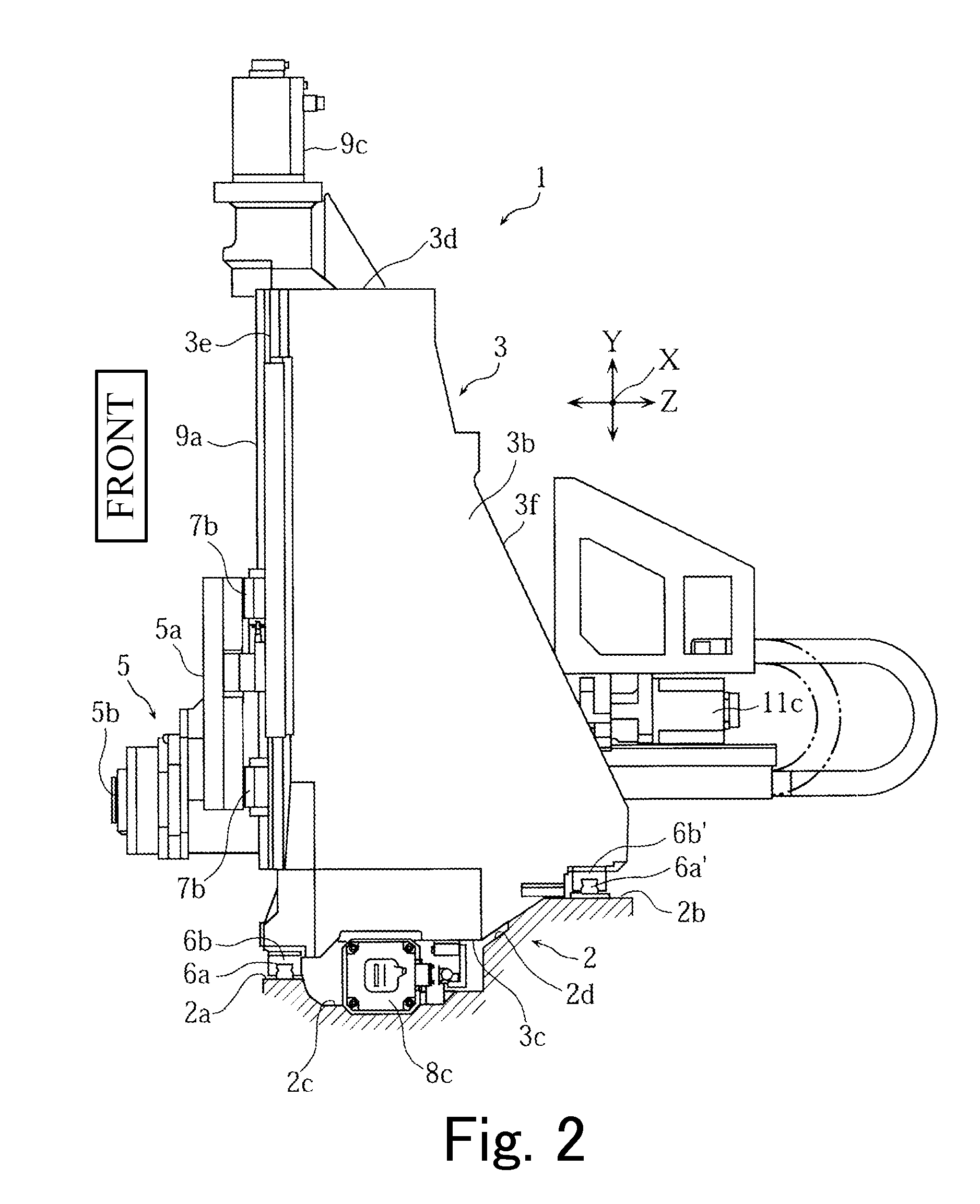
[0033]FIG. 1 to FIG. 4 are views for explaining a horizontal machining center provided with a spindle guide mechanism according to Embodiment 1 of the present disclosure.

[0034]In the drawings, the reference numeral “1” denotes a horizontal machining center (machine tool). The horizontal machining center 1 includes a bed 2, a column 3 mounted on the bed 2 movably in a horizontal direction (in an X-axis direction) when seen from a front side thereof, a saddle 4 supported by the front surface of the column 3 movably in an up-and-down direction (in a Y-axis direction), and a spindle (moving body) 5 supported by the saddle 4 movably in a front and rear direction (in a Z-axis direction).

[0035]On the bed 2, a front rail mounting surfac...


PUM

PropertyMeasurementUnit
angleaaaaaaaaaa
angleaaaaaaaaaa
angleaaaaaaaaaa

Abstract

A moving body guide mechanism of a machine tool includes at least two bar-shaped guide members, and sliders engaged with the two guide members, respectively, movably with respect to the guide members so that a moving body is guided along an axis parallel to a moving axis extending in a longitudinal direction of the guide members. Attaching surfaces of the two guide members or the sliders to the moving body are provided symmetrically across a plane including the axis parallel to the moving axis in such a manner that an angle formed by the attaching surfaces becomes smaller than 180°.

Description

CROSS-REFERENCE TO RELATED APPLICATIONS[0001]The present application claims priority under 35 U.S.C. 119 to Japanese Patent Application No. 2014-033371, filed on Feb. 24, 2014, the content of which is incorporated herein by reference in its entirety.BACKGROUND OF THE INVENTION[0002]1. Field of the Invention[0003]The present disclosure relates to a moving body guide mechanism of a machine tool such as a horizontal machining center for supporting and guiding a moving body thereof such as a spindle in a movable manner.[0004]2. Description of the Related Art[0005]The following description of related art sets forth the inventors' knowledge of related art and certain problems therein and should not be construed as an admission of knowledge in the prior art.[0006]In a horizontal machining center, as a spindle guide mechanism for supporting and guiding a spindle in a horizontally movable manner, there is one disclosed in Japanese Patent No. 4373892, for example. In this conventional spindle...

Claims


Application Information

Patent Timeline
Patent Type & Authority Applications(United States)
IPC IPC(8): B23Q1/70B23Q5/32
CPCB23Q5/326B23Q1/706B23Q1/626B23Q1/017B23Q1/70Y10T409/306664
Inventor HOSHI, TAKASHIKIMURA, HAJIMEYASUMURA, RYOSUKE
Owner DMG MORI CO LTD
Why Eureka
Try Eureka