Apparatus for densifying carbon/carbon composite material

a technology of carbon composite materials and densifying apparatus, which is applied in the direction of chemical vapor deposition coating, metal material coating process, coating, etc., can solve the problems of affecting the densification effect of carbon composite materials, etc., to achieve the effect of reducing energy consumption

Inactive Publication Date: 2015-08-27
DACC CARBON
View PDF8 Cites 6 Cited by
  • Summary
  • Abstract
  • Description
  • Claims
  • Application Information

AI Technical Summary

Benefits of technology

[0014]An aspect of the present invention provides a densifying apparatus that minimize energy consumption when densifying a small amount of preforms or a large amount of preforms.

Problems solved by technology

However, the content of metal silicon in the heat resistant composite material increases, as compared with making a heat resistant material using chemical vapor infiltration or polymer infiltration pyrolysis, so heat resistance and durability are deteriorated.
However, the prior art is suitable for equipment for densifying a plurality of preforms at a time, but the core heater should be operated to maintain the internal temperature of the reaction chamber at 700 to 1300 degrees, even if a small amount of preforms are densified, so a loss of power is too much and it take long time to densify a small amount of preforms.
In particular, when preforms are a small amount of ring-shaped thick discs, it takes too much time to densify the small amount of preforms, and a matrix is formed to a predetermined depth from the surfaces of the preforms and a gas cannot infiltrate to the center in the preforms, so the preforms cannot be filled with the matrix.
As a matrix is not uniformly formed in a preform, the heat resistance and mechanical properties of a heat resistant material made of the preform are poor.
On the other hand, small-sized densifying equipment is expensive and a large cost is required.

Method used


Image

  • Apparatus for densifying carbon/carbon composite material
  • Apparatus for densifying carbon/carbon composite material
  • Apparatus for densifying carbon/carbon composite material

Examples


Embodiment Construction

[0030]Exemplary embodiments of the present invention will now be described in detail with reference to the accompanying drawings.

[0031]Hereinafter, a densifying apparatus according to an embodiment of the present invention will be described with reference to the accompanying drawings.

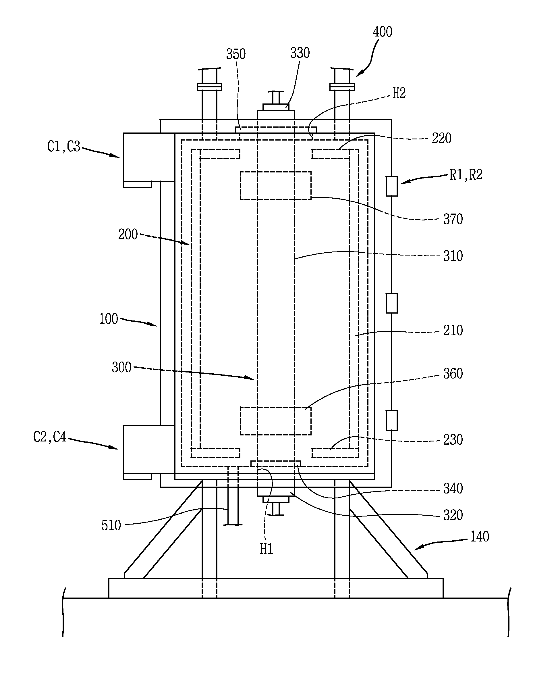
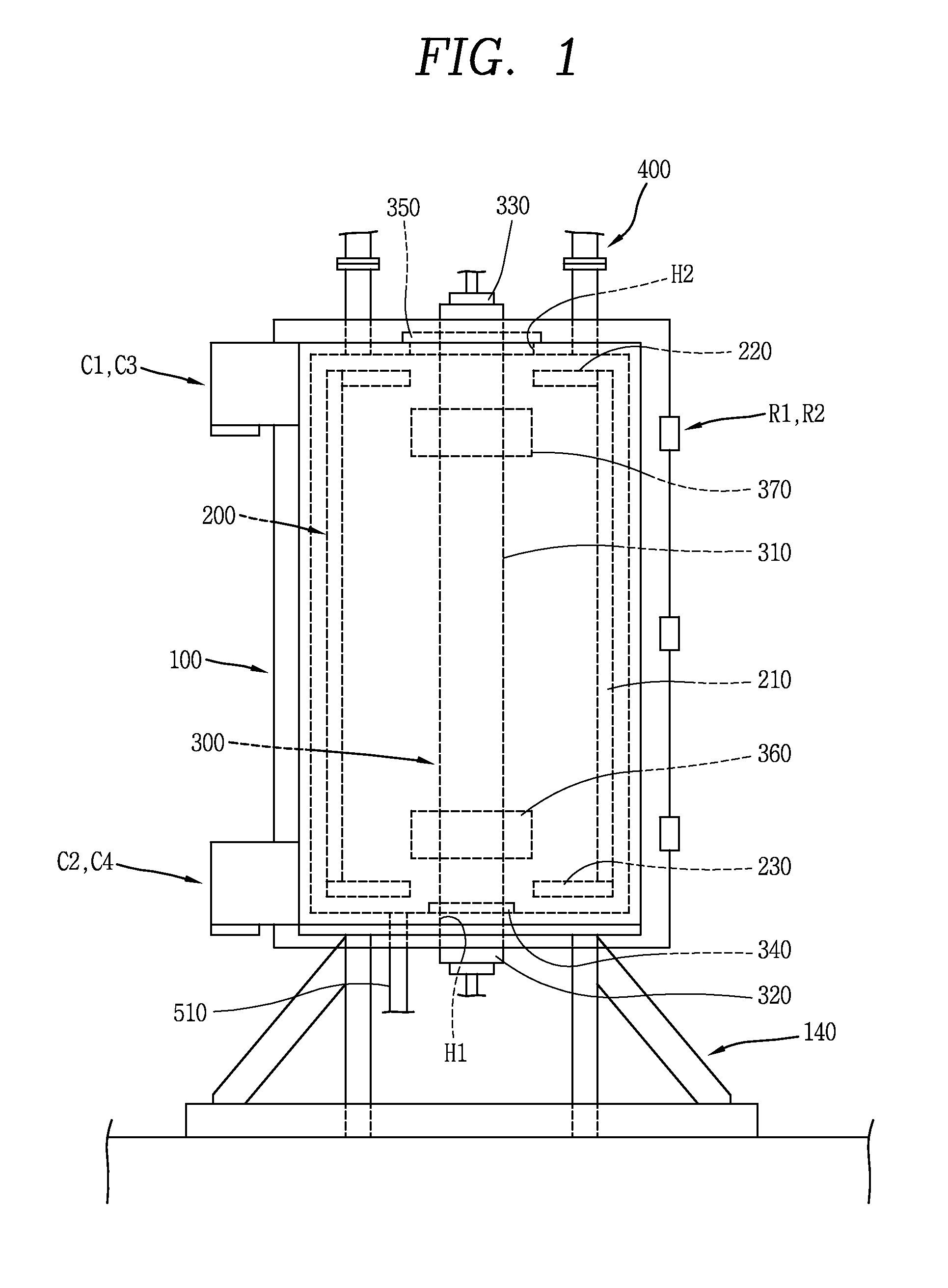
[0032]FIG. 1 is a front view illustrating a densifying apparatus according to an embodiment of the present invention. FIG. 2 is a plan view illustrating the densifying apparatus according to an embodiment of the present invention.

[0033]As illustrated in FIGS. 1 and 2, a densifying apparatus according to an embodiment of the present invention includes a reaction chamber 100, a fixed heater 200, a detachable heater 300, and a gas supply unit 400.

[0034]The reaction chamber 100 may be a cylinder having an internal space, with the top and the bottom closed. For example, the reaction chamber 100 is radially divided into three parts. That is, the reaction chamber is composed of a center body 110 that is the mi...


PUM

PropertyMeasurementUnit
shapeaaaaaaaaaa
widthaaaaaaaaaa
thicknessaaaaaaaaaa

Abstract

A densifying apparatus including: a reaction chamber; a fixed heater is disposed close to the inner wall of the reaction chamber and generating heat; a detachable heater detachably coupled to the reaction chamber and generating heat; and a gas supply unit supplying a gas into the reaction chamber. It is possible to minimize energy consumption when densifying a small amount of preforms or a large amount of preforms and uniformly densify disc preforms having the shape of a thick ring. Further, it is possible to reduce time to density those preforms.

Description

CROSS-REFERENCE TO RELATED APPLICATIONS[0001]This application claims the priority of Korean Patent Application No. 10-2014-0022853 filed on Feb. 26, 2014, in the Korean Intellectual Property Office, the disclosure of which is incorporated herein by reference.BACKGROUND OF THE INVENTION[0002]1. Field of the Invention[0003]The present invention relates to a densifying apparatus.[0004]2. Description of the Related Art[0005]In general, there are, as heat resistant composite materials, a carbon reinforcing silicon carbide composite material (Cf / SiC), a silicon carbide fiber reinforcing silicon carbide composite material (SiCf / SiC), and a carbon fiber reinforcing carbon composite material (Cf / C).[0006]A method of manufacturing a heat resistant composite material is to form a preform by weaving a carbon fiber (Cf) or a silicon carbide fiber (SiCf), and fill silicon carbide (SiC) or carbon (C) that is a component of a matrix in between the fibers in the preform (hereafter, referred to as ‘d...

Claims


Application Information

Patent Timeline
Patent Type & Authority Applications(United States)
IPC IPC(8): C23C16/46C23C16/22
CPCC23C16/22C23C16/46C23C16/045
Inventor CHOI, WOO CHULPARK, JONG HYUNCHO, CHAE WOOKYUN, CHEOL SU
Owner DACC CARBON
Why Eureka
Try Eureka