Hydrant Enclosure With Integral Faucet

Active Publication Date: 2015-08-27
WCM IND INC
View PDF3 Cites 15 Cited by
  • Summary
  • Abstract
  • Description
  • Claims
  • Application Information

AI Technical Summary

Benefits of technology

[0021]It is one aspect of embodiments of the present invention to provide an enclosure with an integrated hydrant. More specifically, one embodiment is a hydrant enclosure comprising a plate. A door is operatively interconnected to the plate. The plate also includes at least one cavity recessed relative to a plate that allows for larger components, such as backflow preventers and control knobs, to be accommodated when the enclosure door is clos

Problems solved by technology

Existing enclosures are rigidly mounted to a wall and are difficult to replace.
One of skill the art will appreciate that this method of repair is labor intensive, time consuming, and inefficient as often only the door is damaged.
In addition, keys that are used to open door locks are often lost, which causes maintenance personnel to pry the door open, which damages the door.
As one of ordinary skill in the art will appreciate, the interconnection of the plate 10 to the back wall of the enclosure constitutes a leak point, wherein water can infiltrate the space behind the encl

Method used


Image

  • Hydrant Enclosure With Integral Faucet
  • Hydrant Enclosure With Integral Faucet
  • Hydrant Enclosure With Integral Faucet

Examples


Embodiment Construction

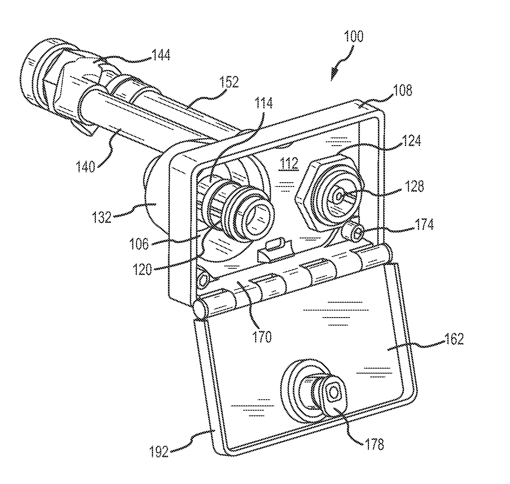
[0069]FIGS. 7-11 show an enclosure 100 with an integrated hydrant of one embodiment of the present invention. The enclosure 100 is defined by a plate 104 with an outwardly-extending lip 108. The plate 104 has an inner surface 112 and an outer surface 116. The plate 104 also has a recess 106 that extends from the inner surface 112 toward the outer surface 116. The plate 104 also includes an opening 124 that receives a control rod and stem screw has shown in FIG. 4. The inner surface 112 is adapted to receive a backflow preventer 120. The backflow preventer 120 is positioned within the recess 106 such that an outer edge of the backflow preventer 120 does not extend from the inner surface 112 to an extent that adversely affects door closure.

[0070]FIGS. 9 and 10 show a rear portion of the enclosure 100. The recess in the plate forms an outwardly-extending protrusion 132, which in one embodiment is frusto-conical. The protrusion 132 has an outer surface that includes an opening (not show...


PUM


Abstract

Provided is an enclosure with an integrated hydrant. The enclosure includes a fluid flow conduit that transfers fluid from a fluid supply tube to a fluid outlet, which may be associated with the backflow preventer. The enclosure has a conduit that carries water from the fluid supply tube to the backflow preventer. Thus, a lower profile, lighter, and more aesthetically pleasing enclosure is provided.

Description

[0001]This application is a continuation-in-part of U.S. patent application Ser. No. 14 / 317,627, filed Jun. 27, 2014, which claims the benefit of U.S. Provisional Patent Application Ser. No. 61 / 841,597, filed Jul. 1, 2013, the entire disclosures of which are incorporated by reference herein.[0002]This application is a continuation-in-part of U.S. Patent Application Serial No. 29 / 503,651, filed Sep. 29, 2014, the entire disclosures of which is incorporated by reference herein.[0003]This application is a continuation-in-part of U.S. Patent Application Serial No. 29 / 503,653, filed Sep. 29, 2014, the entire disclosures of which is incorporated by reference herein.[0004]This application is a continuation-in-part of U.S. Patent Application Serial No. 29 / 514,306, filed Jan. 10, 2015, the entire disclosures of which is incorporated by reference herein.[0005]This application is a continuation-in-part of U.S. Patent Application Serial No. 29 / 514,307, filed Jan. 10, 2015, the entire disclosure...

Claims


Application Information

Patent Timeline
IPC IPC(8): E03B9/02
CPCE03B9/025E03B7/095E03B9/10Y10T137/7043Y10T137/7062F16K27/006F16K31/46Y10T137/5468F16K35/10
Inventor BALL, WILLIAM T.PILARCZYK, ERIC
Owner WCM IND INC
Why Eureka
Try Eureka