
Multiple detection function modularized lighting device

a lighting device and multi-function technology, applied in lighting support devices, television systems, instruments, etc., can solve the problems of complex components of these lighting devices, difficult maintenance, conventional compound products, etc., and achieve the effect of simplifying the overall structur

Active Publication Date: 2015-08-27
CHEN KAIPO
View PDF13 Cites 18 Cited by
  • Summary
  • Abstract
  • Description
  • Claims
  • Application Information

AI Technical Summary

Benefits of technology

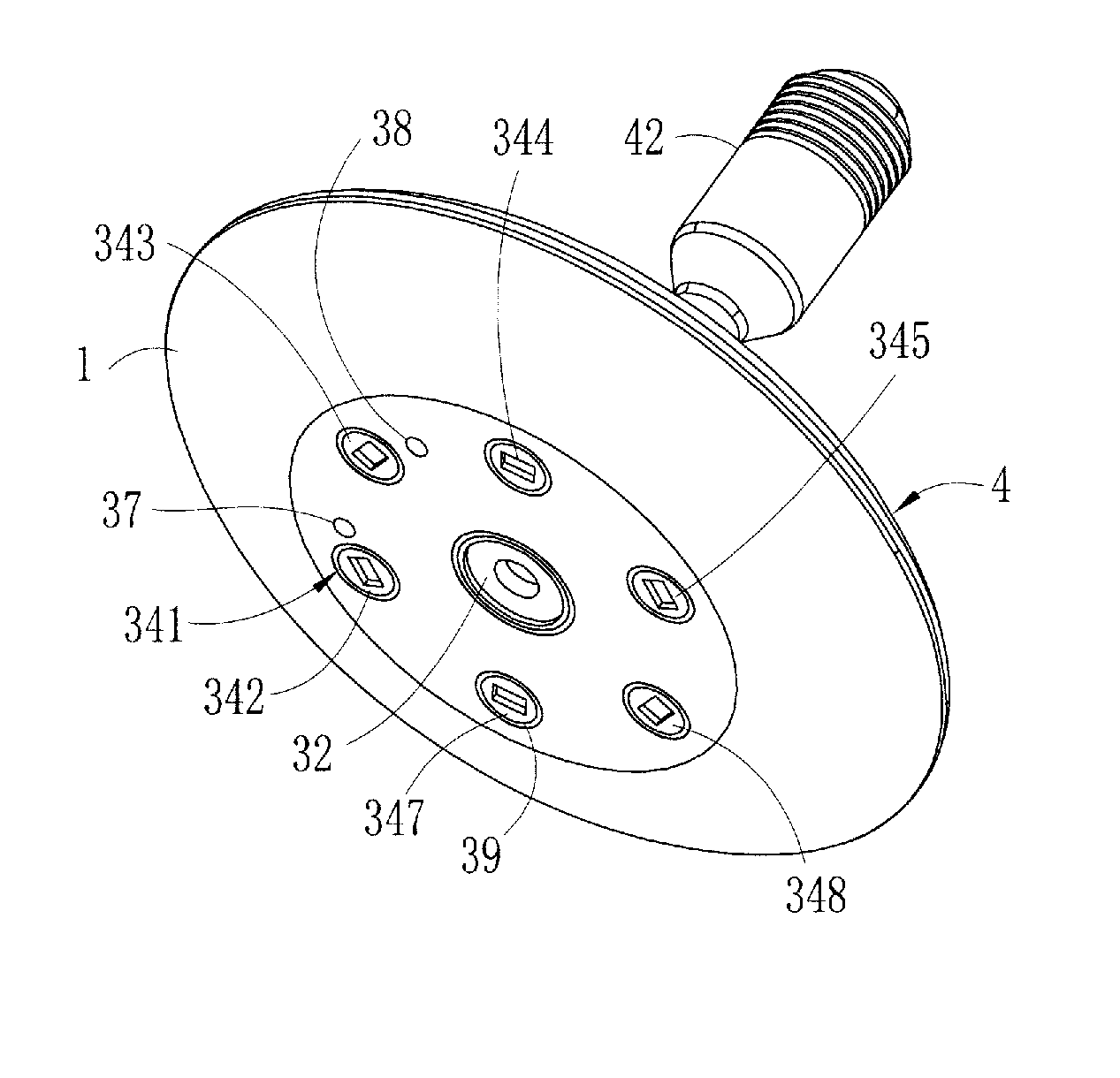
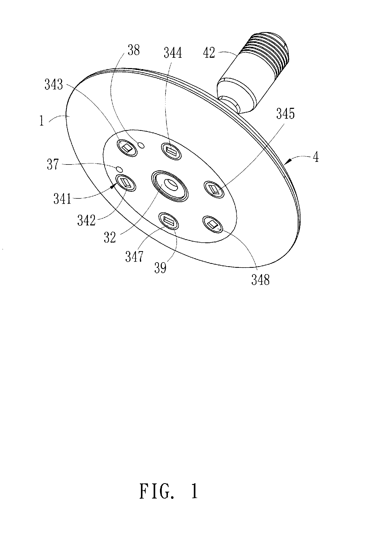
This patent describes a modularized lighting device with multiple functions, including detection, control, photographing, and LED lighting. The device consists of a detection module, control module, photographing module, and LED module that are integrated on a substrate and held in position by a lower housing member and an upper housing member with positioning holes. The detection and photographing modules are completely received and embedded in the positioning holes, which can be separated into different areas using isolation hoods. The lighting device can adjust detection and video recording ranges using a rotary spherical seat. This invention simplifies the overall structure of the lighting device and allows for the activation of different modules based on different data detection needs. The product supply side can also select and change the components of the modules for different applications.

Problems solved by technology

The components of these lighting devices are complicated and maintenance is difficult.
The primary cause may be such that a conventional compound product of the kind discussed above may have a bulky size if a component for detection purposes is included and this is even worse for the inclusion of multiple detection components.
In addition, the reason that no lighting device can be made in this way is that a long term use of an LED would generate a high temperature, which may affect the accuracy of detection and lead to a fault result of detection.

Method used


Image

  • Multiple detection function modularized lighting device
  • Multiple detection function modularized lighting device
  • Multiple detection function modularized lighting device

Examples


Embodiment Construction

[0024]The following descriptions are exemplary embodiments only, and are not intended to limit the scope, applicability or configuration of the invention in any way. Rather, the following description provides a convenient illustration for implementing exemplary embodiments of the invention. Various changes to the described embodiments may be made in the function and arrangement of the elements described without departing from the scope of the invention as set forth in the appended claims.

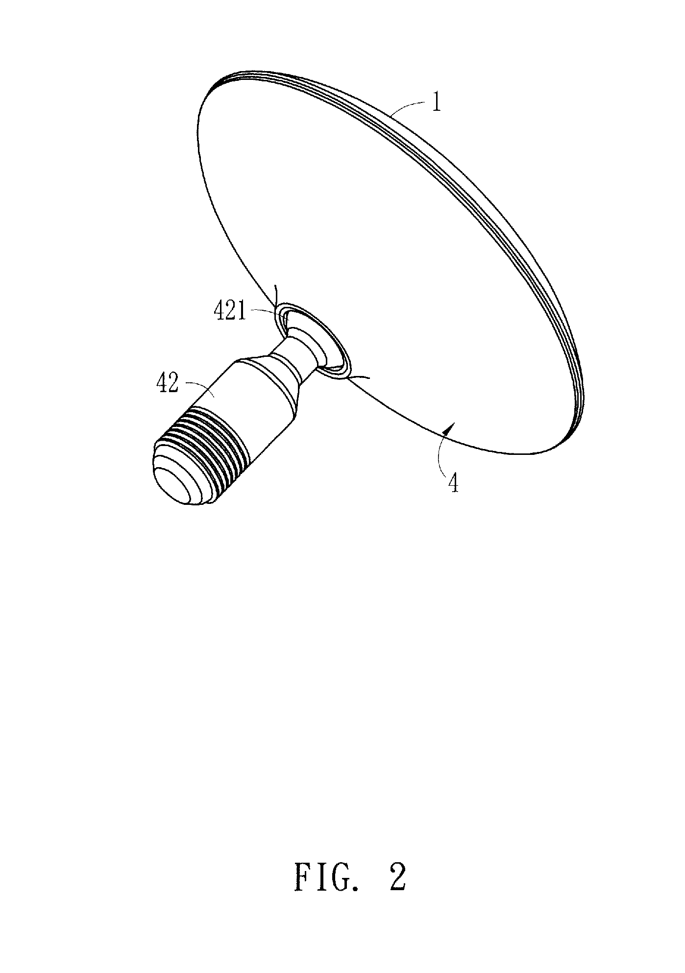
[0025]The present invention provides a multiple detection function modularized lighting device, which as shown in FIGS. 1-4, generally comprises: a lower housing member (4) for electrical connection with a substrate (3). The lower housing member (4) comprises a base (41) comprising a through hole formed through a center thereof. A pivot joint member (42) that has a front end forming a universal joint (421) is received through the center of the base (41) to couple to a pivoting seat (43) so as to be ...


PUM


Abstract

A multiple detection function modularized lighting device includes a substrate on which a photographing module is mounted and also includes an indication module, a detection module, an alarm module, and an LED module that are circumferentially arranged as an annular array along a circumference of the photographing module so that the number of all components can be simplified and integrated on the substrate. An opposite side of the substrate includes a control module mounted thereon to drive all the previous modules. The photographing module and the detection module are received and housed in isolation hoods, which are arranged, through an upper housing member having a plurality of positioning holes being mounted atop a lower casing housing member, to have the photographing module and the detection module embedded in the positioning holes so that the modules on the substrate are respectively set in independent areas defined in the upper housing member.

Description

[0001]This is a continuation-in-part of co-pending U.S. patent application Ser. No. 13 / 220,720 filed on Aug. 30, 2011 and owned by the present applicant.(a) TECHNICAL FIELD OF THE INVENTION[0002]The present invention generally relates to a multiple detection function modularized lighting device, in which various modules are simplified and integrated with a substrate, which when combined with a housing, allows the modules to be arranged in independent areas to achieve the purpose of stabilizing the operations of the modules.(b) DESCRIPTION OF THE PRIOR ART[0003]A lighting fixture that uses LED (Light-Emitting Diode), has various advantages of energy saving, extension of lifespan, and high brightness and is thus widely used in household and workshop applications. To simulate the desire of purchase, various multi-functional compound lighting devices are available in the market, of which the functions generally include temperature detection, gas detection, and remote control. The compon...

Claims


Application Information

Patent Timeline
Patent Type & Authority Applications(United States)
IPC IPC(8): G08B13/196H04N7/18F21V33/00H04N5/225
CPCG08B13/19619H04N5/2252G08B13/19695F21V33/0052H04N7/183F21V23/0464F21V23/0471F21V23/0478G08B15/001G08B5/36G08B21/14F21V21/30G08B13/19617
Inventor CHEN, KAIPO
Owner CHEN KAIPO
Learn More