
Antenna of mobile communication base station and method for controlling same

Active Publication Date: 2015-08-27
KMW INC
View PDF2 Cites 7 Cited by
  • Summary
  • Abstract
  • Description
  • Claims
  • Application Information

AI Technical Summary

Benefits of technology

The patent text describes a new design for the antenna of a mobile communication base station and a way to control it. The design makes it easier and cheaper to install and control, which saves money and space. This new design helps the main system of the base station better manage the antenna, which is important for ensuring good communication.

Problems solved by technology

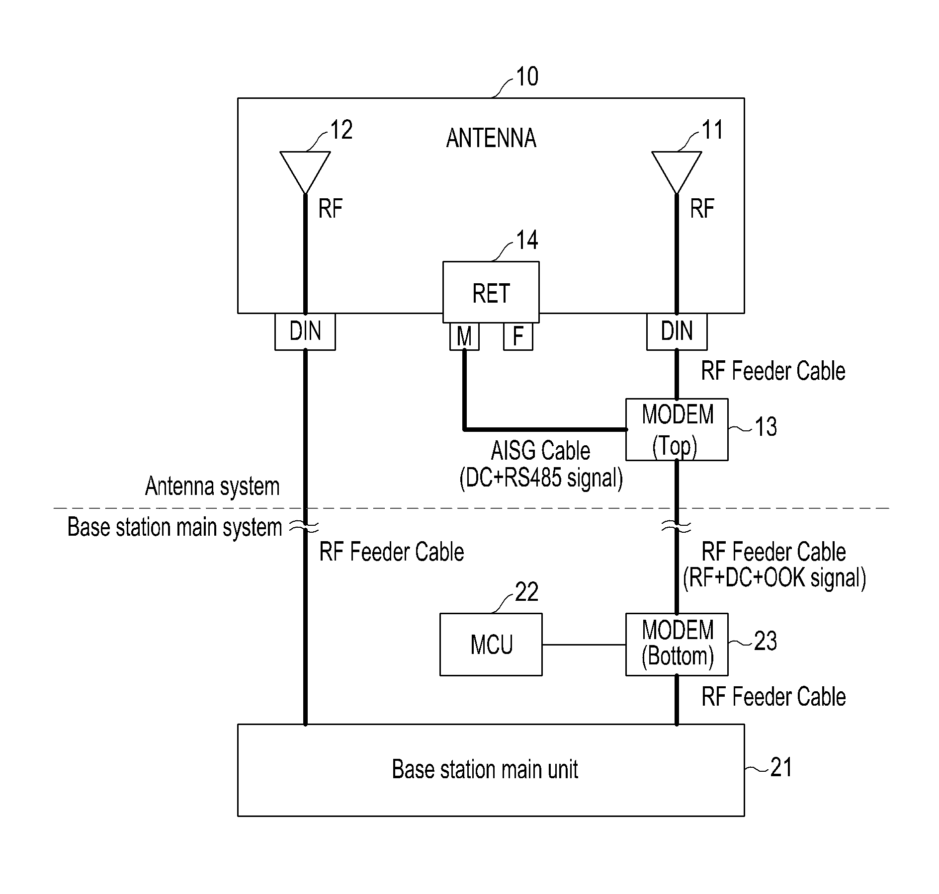
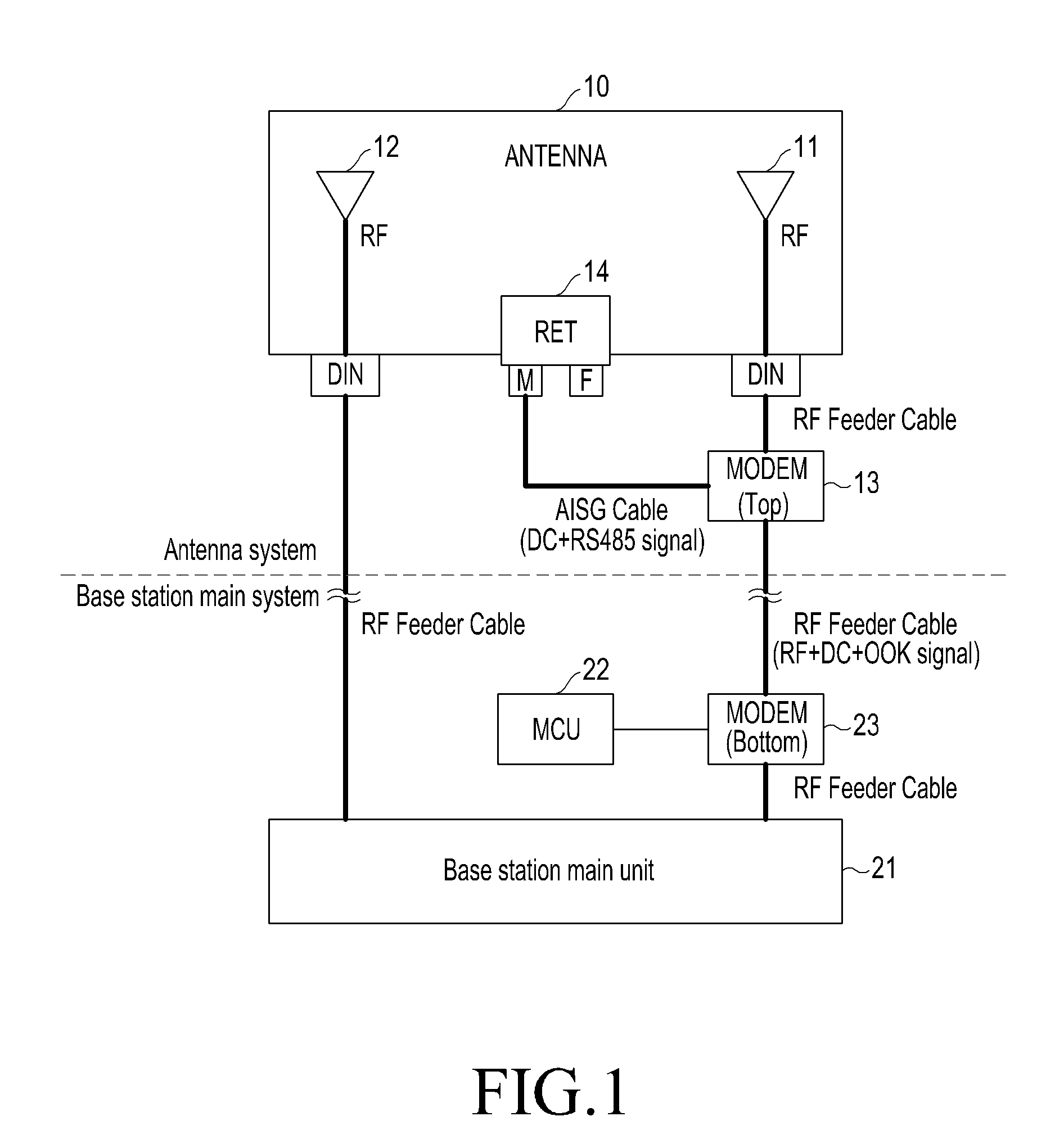
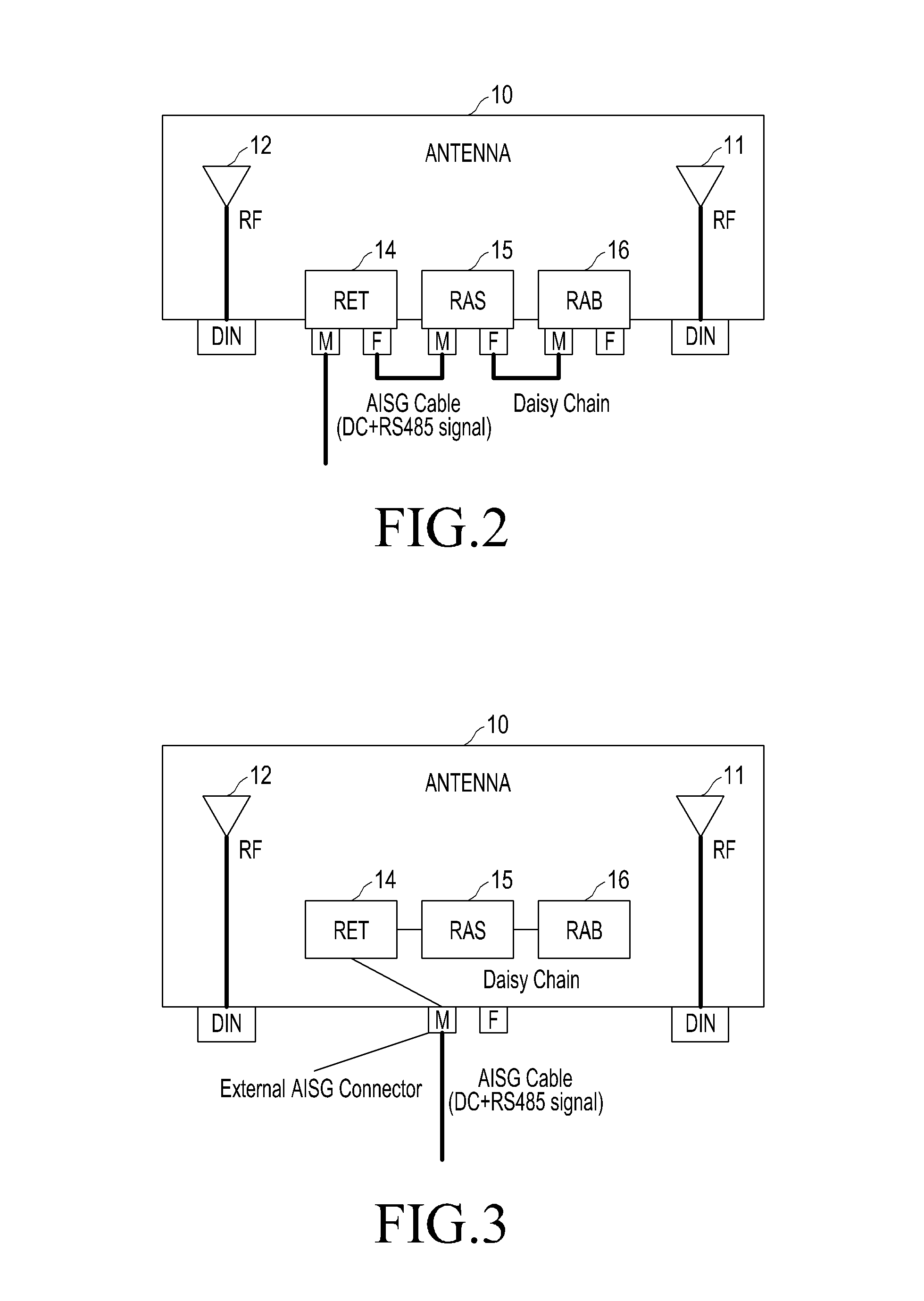
However, according to the current AISG rules, for RET, RAS, and RAB control, the RET device 14, the RAS device 15, and the RAB device 16 have to be provided in the antenna 10 and connected to one another using the AISG cables as described above, thereby causing a cost increase due to device installation and problems involving installation space and weight.
In addition, the main system of the base station has to perform control signal transmission / reception procedures for the RET device 14, the RAS device 15, and the RAB device 16, respectively, thereby resulting in complex communication procedures.
The problems are more serious for the dual, triple, and quad-band antennas.

Method used


Image

  • Antenna of mobile communication base station and method for controlling same
  • Antenna of mobile communication base station and method for controlling same
  • Antenna of mobile communication base station and method for controlling same

Examples


Embodiment Construction

[0028]Hereinafter, exemplary embodiments of the present disclosure will be described in detail with reference to the accompanying drawings. Various specific definitions found in the following description are provided only to help general understanding of the present invention, and it is apparent to those skilled in the art that the present invention can be implemented without such definitions.

[0029]FIG. 4 is a block diagram of an antenna of a mobile communication base station for RET, RAS, and RAB control according to an embodiment of the present disclosure, and a single-band antenna 30 including transmission / reception antenna units 31 and 32 is illustrated in FIG. 4. Referring to FIG. 4, the antenna 30 of the mobile communication base station according to the embodiment of the present disclosure includes: an RET drive unit 341, an RAS drive unit 342, and an RAB drive unit 343 that drive electrical and mechanical apparatuses for adjusting RET, RAS, and RAB, respectively, each includ...


PUM


Abstract

The present invention relates to an antenna of a mobile communication base station, comprising; an RET driving unit, an RAS driving unit, and an RAB driving unit, each comprising a driving motor, for driving electrical and mechanical devices for respectively adjusting RET, RAS and RAB; and multi-function equipment for controlling the driving of the RET driving unit, the RAS driving unit and the RAB driving unit by communicating with a main system of a base station such that at least a control signal for controlling the RET, the RAS, and the RAB is received.

Description

CROSS REFERENCE TO RELATED APPLICATIONS[0001]This application is a continuation of International Application No. PCT / KR2013 / 008261 filed on Sep. 12, 2013, which claims priority to Korean Application No. 10-2012-0101922 filed on Sep. 14, 2012, which applications are incorporated herein by reference.TECHNICAL FIELD[0002]The present disclosure relates to an antenna of a mobile communication base station and, more particularly, to an antenna to which the Antenna Interface Standards Group (AISG) protocol is applied and a control method thereof.BACKGROUND ART[0003]A currently widely used antenna of a mobile communication base station generally has a structure in which a plurality of radiating elements is vertically arranged which can transmit or receive an electric wave using two polarized waves (generally, X-shaped polarized waves) perpendicular to each other. A plane of polarization of the X-shaped polarized waves is basically arranged to be inclined at an angle of +45 degrees or −45 de...

Claims


Application Information

Patent Timeline
IPC IPC(8): H01Q3/04H01Q3/00
CPCH01Q3/04H04W88/08H01Q3/005H01Q1/246H01Q3/32H01Q21/28H04W88/085
Inventor MOON, YOUNG-CHANSO, SUNG-HWANLEE, DONG-HUNWOO, KI-HOON
Owner KMW INC
Learn More